EasyManuals Logo

Rosen Aviation Remote Display System User Manual

Default Icon
43 pages
To Next Page IconTo Next Page
To Previous Page IconTo Previous Page
Page #37 background imageLoading...
Page #37 background image
Rosen Aviation Remote Display System
Document Number: 105478
Revision: A
Date: 04/24/12
Template: 4.2.3-6-FM; Revision A; 16 May, 2005
Page 37 of 43
Description
Section
Category
Comments
Magnetic Effect
15.3
A
Power Input
16
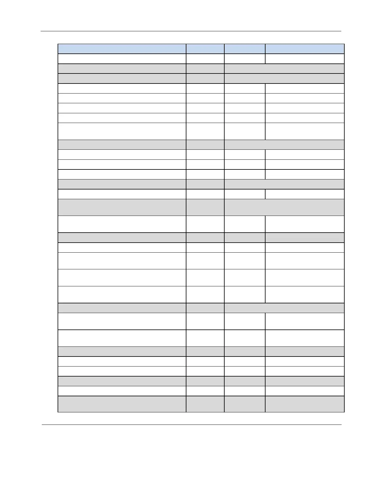
Normal Operating Conditions (DC)
16.6.1
Average Value Voltage (DC)
16.6.1.1
Z
Ripple Voltage (DC)
16.6.1.2
Z
Momentary Power Interruptions (DC)
16.6.1.3
Z (A)
Normal Surge Voltage (DC)
16.6.1.4
Z
Engine Starting Under Voltage Operation
(DC)
16.6.1.5
Z
Abnormal Operating Conditions
16.6.2
Voltage Steady State (DC)
16.6.2.1
Z
Momentary Under Voltage (DC)
16.6.2.3
Z
Abnormal Surge Voltage (DC)
16.6.2.4
Z
Voltage Spike
17
Voltage Spike
17.4
A
Audio Frequency Conducted
Susceptibility
18
AF Conducted Susceptibility- Power
Inputs
18.3.1
Z
Induced Signal Susceptibility
19
Magnetic Fields Induced Into Equipment
19.3.1
AC
Magnetic Fields Induced Into
Interconnecting Cables
19.3.2
AC
Electric Fields Induced Into
Interconnecting Cables
19.3.3
AC
Spikes Induced Into Interconnecting
Cables
19.3.4
AC
Radio Frequency Susceptibility
20
Conducted Susceptibility (CS) 10kHz to
400MHz
20.4
T
Radiated Susceptibility (RS) 100MHz to
18GHz
20.5
T
Emission of Radio Frequency Energy
21
Conducted RF Emission
21.4
M
Radiated RF Emission
21.5
M
Electrostatic Discharge (ESD)
25
Electrostatic Discharge (ESD)
25.5
A
Flammability
26
N/A
Flammability testing in
accordance with 14 CFR

Table of Contents

Questions and Answers:

Question and Answer IconNeed help?

Do you have a question about the Rosen Aviation Remote Display System and is the answer not in the manual?

Rosen Aviation Remote Display System Specifications

General IconGeneral
BrandRosen Aviation
ModelRemote Display System
CategoryMonitor
LanguageEnglish

Related product manuals