34
AA
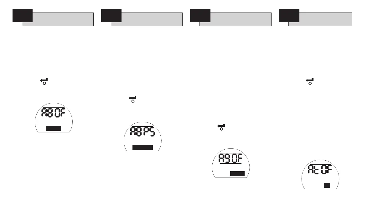
Actuators are delivered with the
interlock facility disabled [OF]
Disabled
.
Refer to the actuator wiring diagram
or PUB002-002 for interlock control
circuits.
To enable remote external interlocks
press the
+
or
-
key.
The display will change to [O
n]
Enabled
.
PRESS THE KEY.
The displayed option will flash (stored)
indicating that it has been set.
Note: If interlocking is required in only
one direction, it will be necessary to
connect a link between the actuator
terminals associated with the other
direction. Refer to wiring diagram.
The actuator can be set to carry out a
partial stroke test using a signal applied
to the open interlock input to initiate
a partial stroke test. Refer to wiring
diagram.
The default for partial stroke/interlocks
is [OF]
Disabled
.
To enable partial stroke testing press
the
+
or
-
key.
The display will change to [PS]
Partial
Stroke
.
PRESS THE KEY.
The displayed option will flash (stored)
indicating that it has been set.
To access partial stroke test settings
PRESS THE m KEY.
Refer to Appendix A, page 84 for
instructions on partial stroke settings.
Where a high level of safety integrity
is required, Conditional Control can
be configured. In this mode two
discreet signals are required for remote
operation. Remote control will be
conditional on both a control signal
(open or close) and the appropriate
interlock signal being applied
simultaneously. Failure of either or a
spurious signal will not cause operation.
Interlocks [A8] must be set [O
n]
Enabled
. Interlock signals are not
required for local operation.
The default setting for conditional
control is [OF]
Disabled
. To enable
conditional control press the
+
or
-
key.
The display will change to [On]
Enabled
.
PRESS THE KEY.
The displayed option will flash (stored)
indicating that it has been set.
The default setting for Torque Switch
Bypass is [OF]
Off
, the torque switches
are not bypassed during the unseating
movement.
To bypass the torque switches during
the unseating movement press the
+
or
-
key.
The display will change to [O
n].
PRESS THE KEY.
The displayed option will flash (stored)
indicating that it has been set.
The torque switches will be bypassed
from closed limit to 5% open when
opening and from open limit to 95%
when closing. Bypassing the torque
switches makes torque in excess of
rated and up to actuator stall available
for unseating a ‘‘sticky’’ valve. Outside
these positions the torque setting will
revert to the values set for [tC]
Close
Torque
, see page 22 and [tO]
Open
Torque
, page 23.
Interlocks Partial Stroke
A8 A8
Conditional Control
A9
Torque Switch Bypass
At
Interlocks
Disabled
Interlocks
Partial Stroke
Conditional
Control: Disabled
Torque Switch
Bypass: Off

 Loading...