37
AA
Setting instructions for
actuators including a Folomatic
proportional controller for use in
analogue valve position control.
The Folomatic is an optional
control device. Check actuator
wiring diagram for inclusion.
Before setting the parameters for
Option Folomatic ensure Remote
Control Source [Od] has been
selected to [bo] in Section 9.7.
Folomatic set up screens will be
automatically displayed when the
option is fitted. Refer to actuator wiring
diagram.
This instruction lists the Folomatic
function displays in their sequence and
assumes that all Folomatic functions are
to be checked/set.
The actuator should be selected in Local
or Stop with the analogue input signal
connected to terminals 26 (+ve) and
27 (–ve) (refer to wiring diagram).
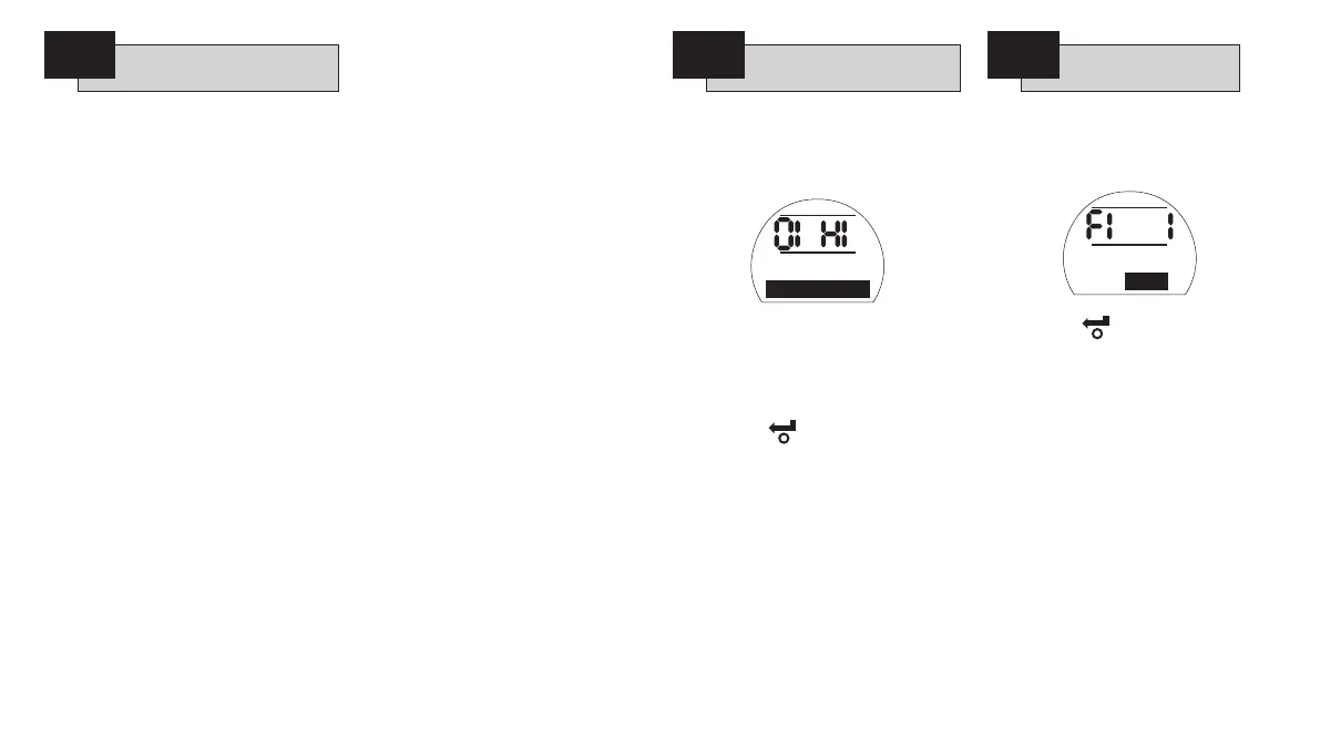
Before commissioning of the Folomatic
functions can begin, the Folomatic
Feedback must be set to suit the
applied set point signal.
With [HI] displayed, a 20mA signal will
correspond to the valve opening.
If a high input signal is required to
correspond to valve closing use the
+
or
-
key to change to [LO]
CL=20mA
.
PRESS THE KEY.
The displayed option will flash (stored)
indicating that it has been set.
If setting [OI] is modified after
commissioning the Folomatic, it will
be necessary to recommission the
Folomatic.
Press the
m key to access the
Folomatic set-up display menus.
Using the
+
or
-
key select [ l]
Current
for current input signal or [ U]
Voltage
for voltage input signal.
PRESS THE KEY.
The displayed option will flash (stored)
indicating that it has been set.
The signal type selected will determine
what is displayed on the input signal
range screen [Fr]
Analog Signal
.
Press the
k key to display:
[Fr]
Analog Signal
.
Analog Feedback
CL=4ma OP=20mA
9.6
Option Folomatic –
Analogue Control
Folomatic Feedback
OI
FI
Analogue
Signal Type
Analog Signal
Type: Current

 Loading...