CompTrol Interface V4.0.x | Issue 21-05-2021 | 1000932 115
Appendix II: Start-up Report
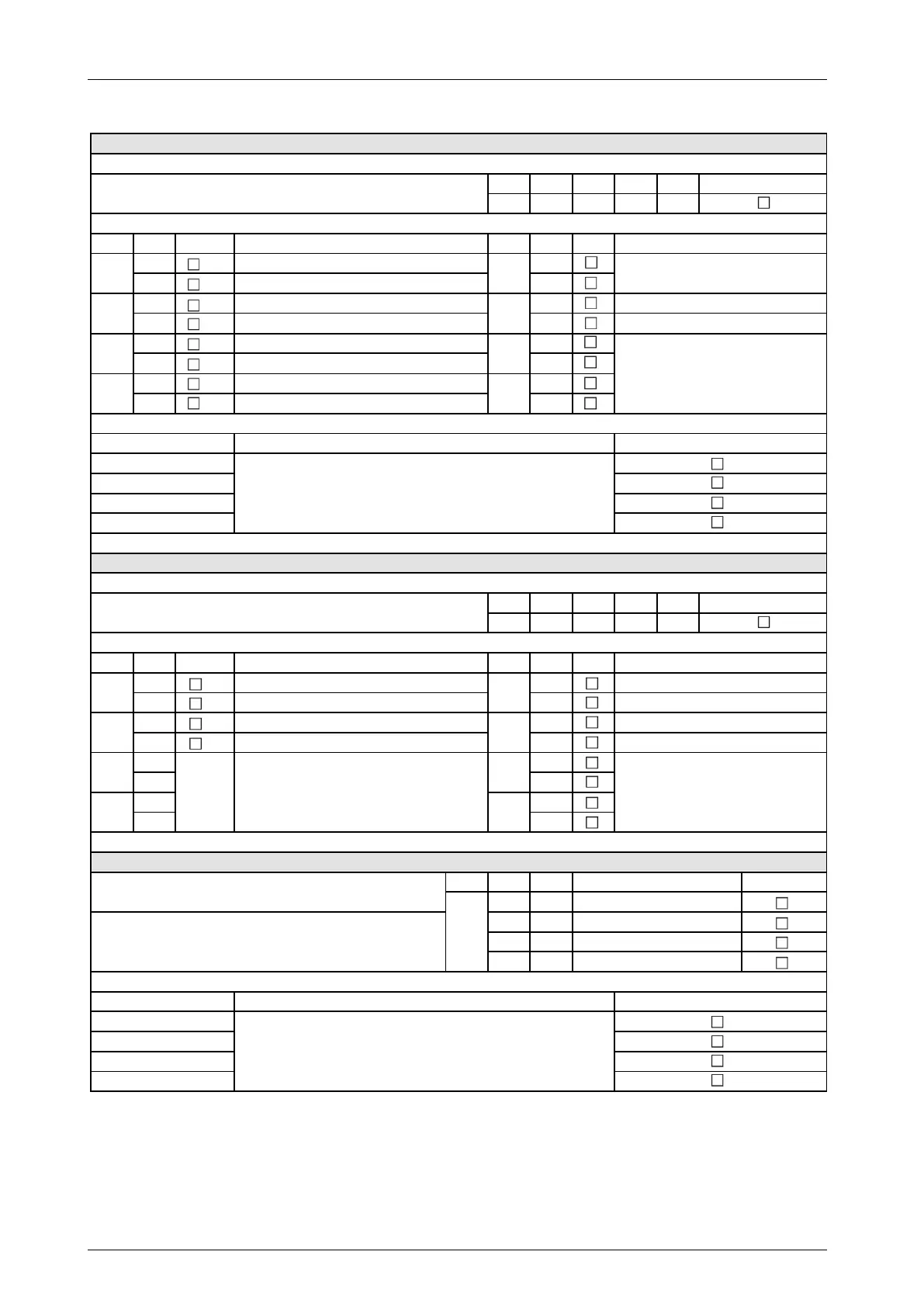
Set program 2 via DIP switches
(check box as applicable)
Safety instruction: Before setting the DIP switches, disconnect the switch gear cabinet and Interface from the electrical supply.
DIP S1-1 S1-2 S1-3 S1-4
Pos. OFF ON OFF OFF
DIP Pos. Function DIP Pos. Function
OFF
Slave
OFF
ON
Master
ON
OFF
X4b: Compressor signal; X4c: Window cont. signal
OFF
All digital outputs (NO)
ON
X4b: Operating signal; X4c: Window contact signal
ON
All digital outputs (NC)
OFF
AUTO ON: Window contact OFF
ON
AUTO ON: Window contact ON
OFF
Inoperative
OFF
ON
Automatic fan speed control
ON
Set program 3 via DIP switches
(check box as applicable)
Safety instruction: Before setting the DIP switches, disconnect the switch gear cabinet and Interface from the electrical supply.
DIP S1-1 S1-2 S1-3 S1-4
Pos. ON ON OFF OFF
DIP Pos. Function DIP Pos. Function
OFF
Slave
OFF
Inoperative
ON
Master
ON
Forced mode
OFF
X4b: Compressor signal; X4c: Temp. signal
OFF
All digital outputs (NO)
ON
All digital outputs (NC)
OFF OFF
ON ON
OFF OFF
ON ON
Program 3: Set DIP switches for temperature limit alarm
(check box as applicable)
DIP S2-3 S2-4
OFF OFF
ON OFF
OFF ON
ON ON
For setting the analog signal, see Set analog signal at analog input X3.
For setting the analog signal, see Set analog signal at analog input X3.
Note: The temperature limit alarm can only be set in program
Description of temperature limit alarm:
If the temperature limit value is exceeded, a status signal is
emitted at digital output X4c-K3.
S2-2
S2-3
S2-4
S2-5
S2-6
S2-7
S2-8
To set the 7-segment display, see table:
7-segment display: Set DIP switches to
display temp. setpoint definition.
S2-1
Inoperative, DIP switch setting is always
OFF
Description of program 2:
Temperature setpoint definition with window contact function
Description of program 3: Temperature setpoint definition for
equipment rooms with limit alarm
Program 3 activated
S2-1
S2-2
S2-3
S2-4
S2-5
S2-6
S2-7
S2-8
To set the 7-segment display, see table:
7-segment display: Set DIP switches to
display temp. setpoint definition.
To set the DIP switches for the temperature limit
alarm, see the following table:
Program 3: Set DIP switches for temperature limit
Temperature limit value [°C]