22 CompTrol Interface V4.0.x | Issue 21-05-2021 | 1000932
Product description
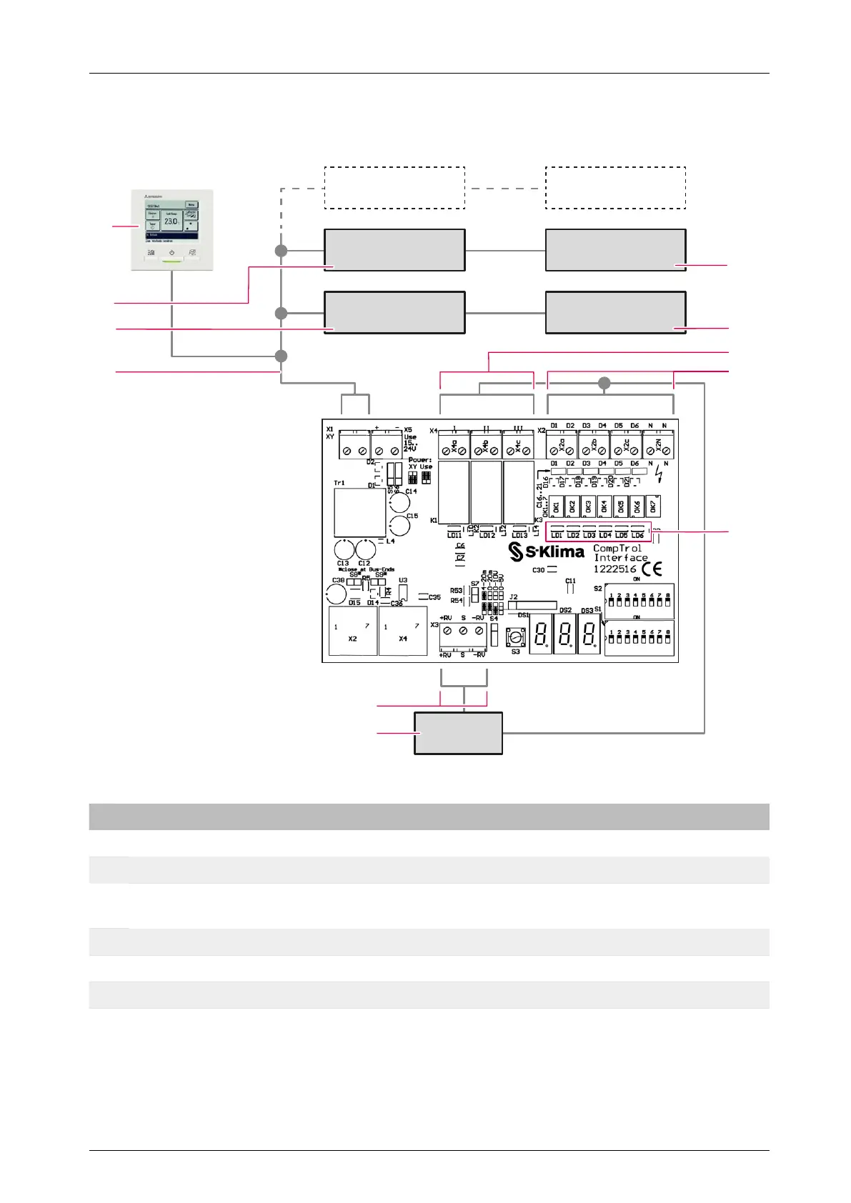
4.8 CompTrol Interface connection diagram
IU 3 OU 3
IU 2 OU 2
IU 1
BMS
OU 1
1
2
3
4
5
6
7
9
10
8
11
Figure 5: CompTrol Interface connection diagram
No. Name No. Name
1 2nd outdoor unit 2 1st outdoor unit
3 Volt-free digital outputs 4 Digital inputs
5
LEDs for indicating the status of digital
inputs
6
Control unit of building services manage-
ment system (BMS)
7 Analog input 8 X/Y remote control bus
9 1st indoor unit 10 2nd indoor unit
11 Wired remote control RC-EX1 or RC-EX3 - -