80 CompTrol Interface V4.0.x | Issue 21-05-2021 | 1000932
Program 9 – direct frequency request with cascading
0
10
20
f
min
f
max
Heating
f
max
Cooling
50
60
70
0 1 1,4 1,8 2,2 2,6 3,0 3,4 3,8 4,2 4,6 5,0 5,4 5,8 6,2 6,6 7,0 7,4 7,8 8,2 8,6 9,0 9,4 9,8 10
Compressor frequency f
[Hz]
Voltage [V DC]
0 0,5 0,7 0,9 1,1 1,3 1,5 1,7 1,9 2,1 2,3 2,5 2,7 2,9 3,1 3,3 3,5 3,7 3,9 4,1 4,3 4,5 4,7 4,9 5
0 2 2,8 3,6 4,4 5,2 6,0 6,8 7,6 8,4 9,2 10 10,8 11,6 12,4 13,2 14 14,8 15,6 16,4 17,2 18 18,8 19,6 20
0 5,6 6,2 6,9 7,5 8,2 8,8 9,4 10,1 10,7 11,4 12 12,6 13,3 13,9 14,6 15,2 15,8 16,5 17,1 17,8 18,4 19 19,7 20
Voltage [V DC]
Current [mA]
Current [mA]
Type of input signal 0-5 V DC
Type of input signal 0-20 mA
Type of input signal 4-20 mA
Type of input signal 0-10 V DC
40
30
Heating: 1st outdoor unit Heating: 2nd outdoor unit
Signal range A Signal range B
Legend
Cooling
: 1st outdoor unit
Cooling
: 2nd outdoor unit
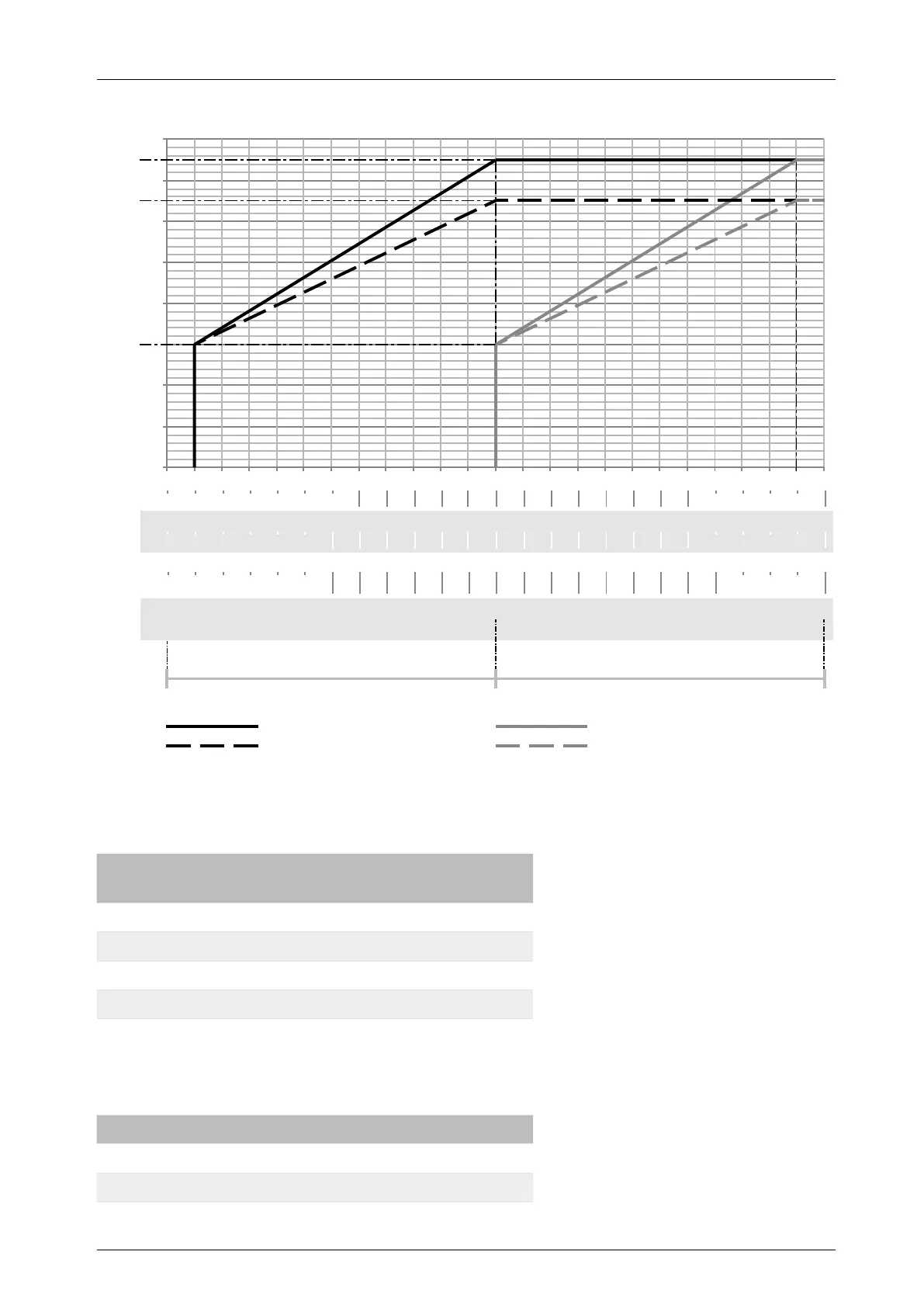
Figure 18: Direct frequency request with cascading without signal overlap
For cascading without signal overlap, only the 1st outdoor unit is controlled by an external analog
signal between the following signal ranges:
Analog signal type Signal range of 1st outdoor
unit
0-10 V DC 1 to 5.4 V DC
0-5 V DC 0.5 to 2.7 V DC
0-20 mA 2 to 10.8 mA
4-20 mA 5.6 to 12.6 mA
Table 57: Direct frequency request with cascading without signal overlap – signal range of 1st outdoor unit
At and above the following analog signals, the 2nd outdoor unit also starts up, until the maximum
compressor frequency is reached:
Analog signal type Signal of 2nd outdoor unit
0-10 V DC 5.4 V DC
0-5 V DC 2.7 V DC