CompTrol Interface V4.0.x | Issue 21-05-2021 | 1000932 19
Product description
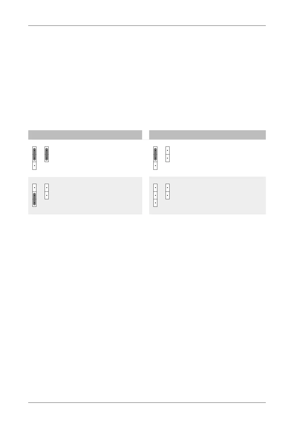
4.3.1 Pin headers S8 and S9
The position of the jumpers on pin headers S8 and S9 determines whether the CompTrol Inter-
face is in the middle or at the end of the CompTrol Interface bus. The pin headers only need to be
set if the CompTrol Interface is connected to a CompTrol Master (see CompTrol Master TM).
4.4 Types of connection
4.4.1 Analog input X3
An analog signal (4 to 20 mA, 0 to 20 mA, 0 to 5 V DC, or 0 to 10 V DC) at analog input X3-S
determines the temperature or frequency setpoint, depending on which program is selected.
The analog signal uses the ground connection X3-(-RV) as a reference.
The position of the jumpers on pin headers S4 and S7 determines the current analog signal type.
S4 S7 Analog signal type S4 S7 Analog signal type
4-20 mA 0-20 mA
0-10 V DC 0-5 V DC
Table 6: Analog signal type
The DC signal is evaluated proportionally at analog input X3-S. The referenced value tables are
program-dependent and described together with the corresponding program.
4.4.2 Digital inputs X2a to X2N
The assignment of digital inputs varies depending on the program, and largely determines the
behavior of the selected program.
All digital inputs are electrically isolated. The input voltage range is 20 V DC to 130 V DC or
24 V AC to 230 V AC. The current status of the digital inputs is indicated by LEDs (LD1 to LD6).
4.4.3 Digital outputs X4a to X4c
Each of the three digital outputs X4a-I, X4b-II, and X4c-III is designed as a volt-free relay contact.
They have a load capacity of 230 V AC/130 V DC, 0.5 A. The switched state of the relays is indi-
cated by LEDs (LD11 to LD13). A lit LED indicates that the corresponding relay is energized and
the contact is closed.
A relay’s switched state changes when the condition for a signal is met. You can congure which
signal is supplied at each output for your program using DIP switch S2-2. The switching function
of the relays can be inverted with DIP switch S2-6. See descriptions of the individual programs for
more details.