CompTrol Interface V4.0.x | Issue 21-05-2021 | 1000932 79
Program 9 – direct frequency request with cascading
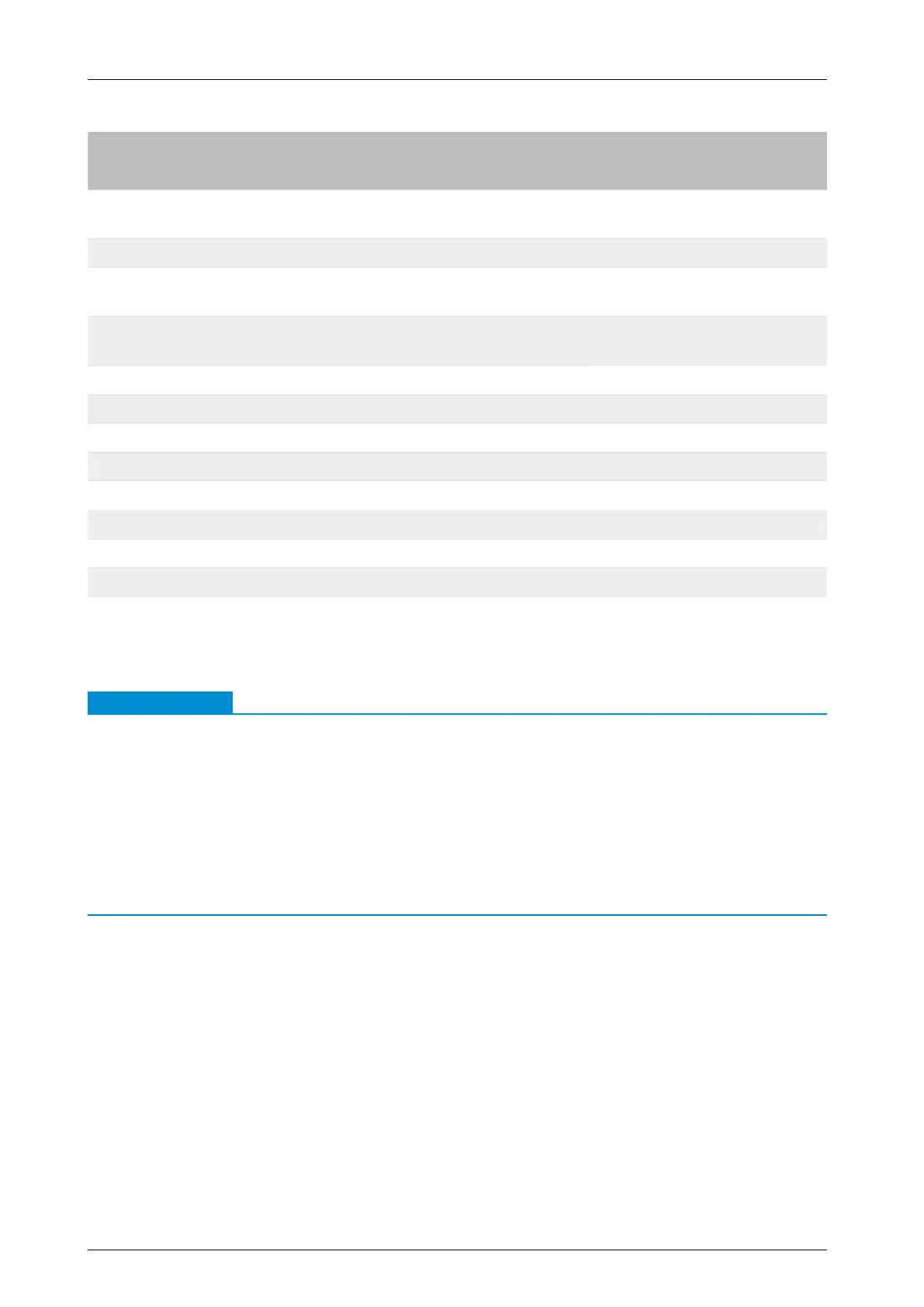
DIP switch Outdoor unit model
S1-5 S1-6 S1-7 S1-8 FDC outdoor unit SRC outdoor unit
OFF OFF ON OFF –
SRC40ZSX-S/ZSX-W
SRC50ZSX-S/ZSX-W
ON OFF ON OFF FDC71VNX –
OFF ON ON OFF
FDC100VN/VNA/VNA-W/VS/VSA/
VSA-W
–
ON ON ON OFF
FDC125VNX/VNX-W/VS/VSX/VSX-W
FDC140VNX/VNX-W/VS/VSX/VSX-W
–
OFF OFF OFF ON – –
ON OFF OFF ON – –
OFF ON OFF ON – –
ON ON OFF ON FDC125VN/VNA/VNA-W/VSA/VSA-W –
OFF OFF ON ON FDC140VN/VNA/VNA-W/VSA/VSA-W –
ON OFF ON ON FDC71VNX-W –
OFF ON ON ON – SRC60ZSX-S/ZSX-W
ON ON ON ON FDC200/250VSA –
Table 56: Setting the outdoor unit model with DIP switches S1-5 to S1-8
15.4 Analog input
Note
●
When running program 9, also set DIP switch SW4-3 on the outdoor unit PCB of the FDC out-
door unit to ON (see FDC series Technical Manual).
●
If there is no input voltage, e.g. due to a broken wire or open input, a frequency of 0 Hz is
transferred.
●
Analog input X3-S is only evaluated if a signal is applied to digital input X2b-D4 (see “5.1
Functions of analog input X3” on page 23).
●
Analog signal conguration must always begin at 0 V DC or 0 mA, to prevent signal distortion
due to electrical induction.
Cascading without signal overlap
The diagram below shows the control behavior of two CompTrol Interface expansion modules for
actuating two outdoor units each with a maximum frequency fmax Heating of 75 Hz without signal
overlap. The compressor frequencies are controlled by the analog signals and depend on the
outdoor unit models set via DIP switches S1-5 and S1-8. The compressor frequencies fmin, fmax
Heating, and fmax Cooling are permanently set for the outdoor unit in question.