98 CompTrol Interface V4.0.x | Issue 21-05-2021 | 1000932
Installing the CompTrol Interface expansion module
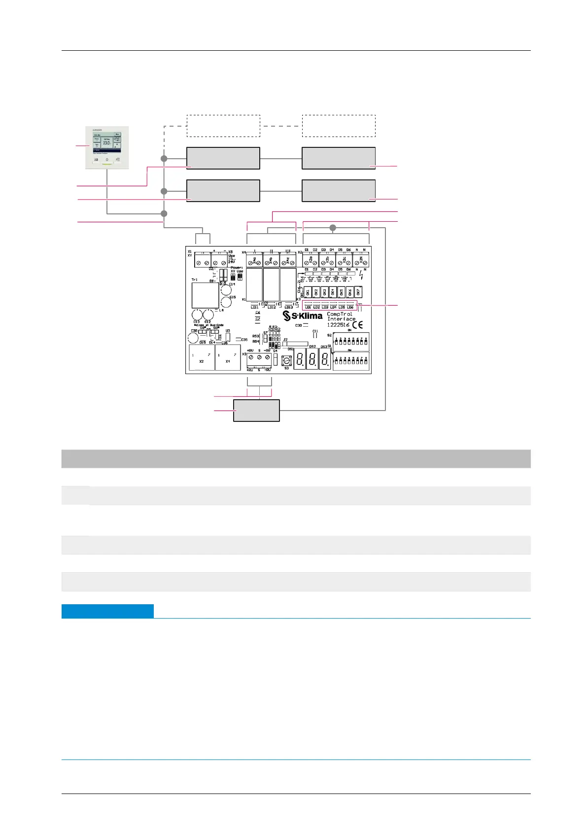
17.4 Installing and connecting the CompTrol Interface expansion module
IU 3 OU 3
IU 2 OU 2
IU 1
BMS
OU 1
1
2
3
4
5
6
7
9
10
8
11
Figure 24: CompTrol Interface connection diagram
No. Name No. Name
1 2nd outdoor unit 2 1st outdoor unit
3 Volt-free digital outputs 4 Digital inputs
5
LEDs for indicating the status of digital
inputs
6
Control unit of building services manage-
ment system (BMS)
7 Analog input 8 X/Y remote control bus
9 1st indoor unit 10 2nd indoor unit
11 Wired remote control RC-EX1 or RC-EX3 - -
Note
●
A wired remote control must be installed in the X/Y remote control bus in which a CompTrol
Interface is to be used.
●
The cable for the X/Y remote control bus must be looped through and the shield applied to
both sides.
Do not set any neutral points or install any junction boxes!
●
Analog input X3-S is not electrically isolated.
When using several CompTrol Interfaces, make sure that each one receives its own analog
signal. If necessary, use an isolation amplier on site.
●
The maximum length of the cable for the X/Y remote control bus to the indoor unit is 120 m.