CompTrol Interface V4.0.x | Issue 21-05-2021 | 1000932 99
Installing the CompTrol Interface expansion module
IMPORTANT
Damage to the CompTrol Interface by reversing the polarity of terminals X5-(+) and X5-(-).
●
Ensure the correct polarity for terminals X5-(+) and X5-(-).
Notes on replacing an older CompTrol Interface III k with a version V4.0.x CompTrol Inter-
face
IMPORTANT
The CompTrol Interface can be damaged by incorrect terminal assignment when replacing
an older CompTrol Interface III k with a version V4.0.x CompTrol Interface.
●
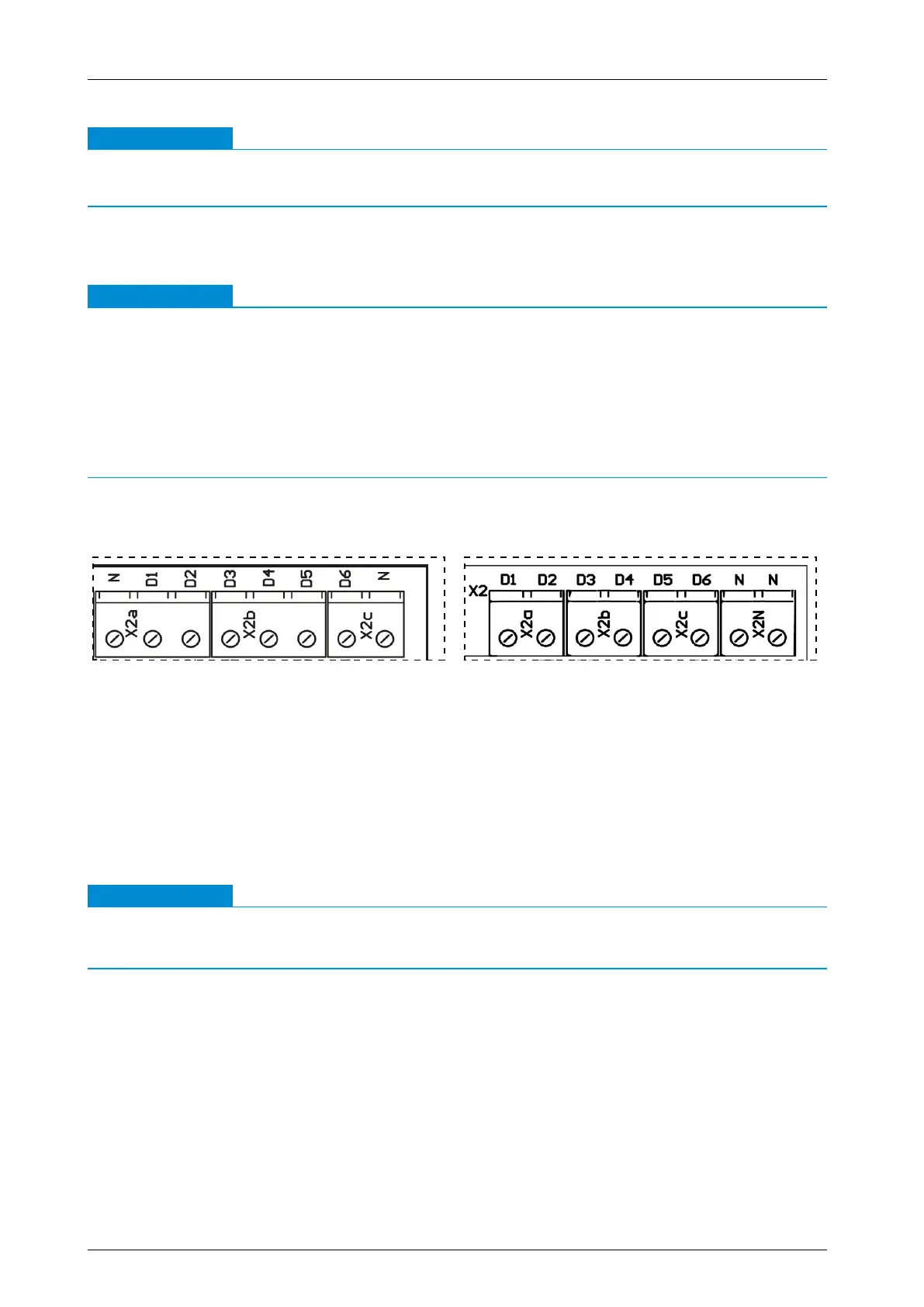
Make sure that the terminals of digital inputs X2a-D1, X2a-D2, X2b-D3, X2b-D4, X2c-D5,
X2c-D6 and neutral wire X2N-N are correctly assigned on the CompTrol Interface V4.0.x (see
diagrams below).
●
Make sure that the terminals on X3-S and X3-(-RV) at analog input X3 of the CompTrol Inter-
face V4.0.x are correctly assigned. The LED+ and LED- terminals are not required.
Terminal assignment of CompTrol Interface III k Terminal assignment of CompTrol Interface
V4.0.x
Requirements
– Switch o the electrical supply to the aected system and signal lines.
Procedure
1. Hook the CompTrol Interface onto the DIN rail with the upper hook of the DIN rail holder at a
suitable location in the switch gear cabinet.
2. Push the CompTrol Interface down onto the DIN rail until the spring-mounted DIN rail catch
clicks audibly into place on the DIN rail.
IMPORTANT
The CompTrol Interface will malfunction if pin headers S5 and S6 are connected to a jumper.
●
Never connect pin headers S5 and S6 to a jumper.
3. Set jumpers on pin headers S5 and S6 (see “4.2 CompTrol Interface electrical supply” on
page 18).
4. Set jumpers on pin headers S4 and S7 (see “4.4.1 Analog input X3” on page 19).
5. Set DIP switches S1-1 to S1-4 according to “Table 7: Program selection via DIP switches” on
page 21.
6. Set the desired functions for your selected program using DIP switches S2-1 to S2-6.
7. Connect the CompTrol Interface as shown in the connection diagram (see “Figure 5: CompT-
rol Interface connection diagram” on page 22).