96 CompTrol Interface V4.0.x | Issue 21-05-2021 | 1000932
Installing the CompTrol Interface expansion module
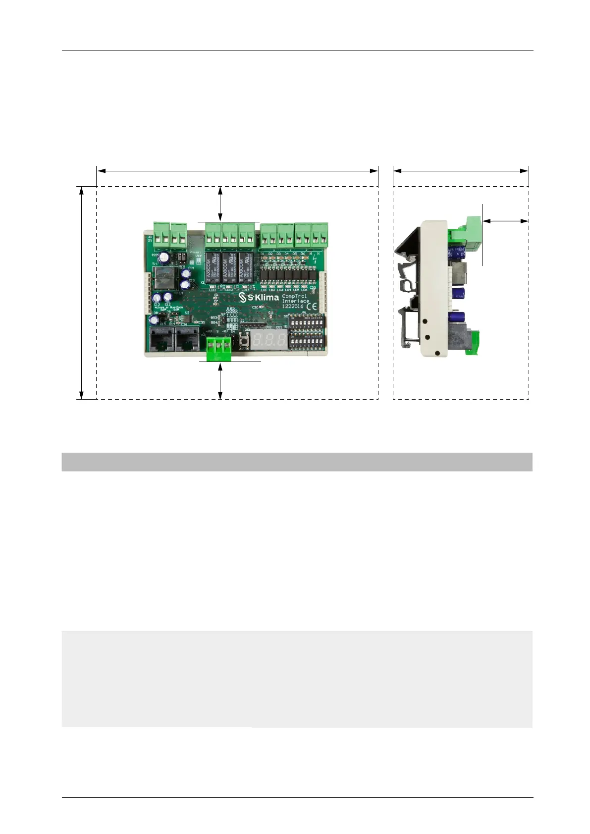
17.2 Service and installation clearance
The diagrams below show the minimum distances to be kept between the CompTrol Interface and
walls or other objects when mounting on a DIN rail in a switch gear cabinet.
All dimensions in mm.
15
15
20
Figure 23: Plan view and side view of the CompTrol Interface with depiction of installation clearances
17.3 Cablerequirements
Connection Designation Cablerequirements Notes
X/Y remote control bus X1-X
X1-Y
Min. LiYCY data cable
(CAT 5); recommended:
LiYCY (TP) data cable
(CAT 5)
–
Core number: 2
–
Conductor size: see Mit-
subishi Heavy Indus-
tries: Quick construction
site guide
–
Max. line length: see
section “21 Technical
data” on page 107
Electrical supply (when not
combined with a CompTrol
Master) and communication
are achieved via the cable of
the X/Y remote control bus.
Bus connections
(CompTrol Master)
X2
X4
Min. patch cable (CAT 5);
not a crossover cable
–
Connector: RJ45
–
Assignment: 1:1
–
Max. line length:
unshielded 1 m;
shielded 25 m
Bus connection for connecting
to a CompTrol Master.