118 CompTrol Interface V4.0.x | Issue 21-05-2021 | 1000932
Appendix II: Start-up Report
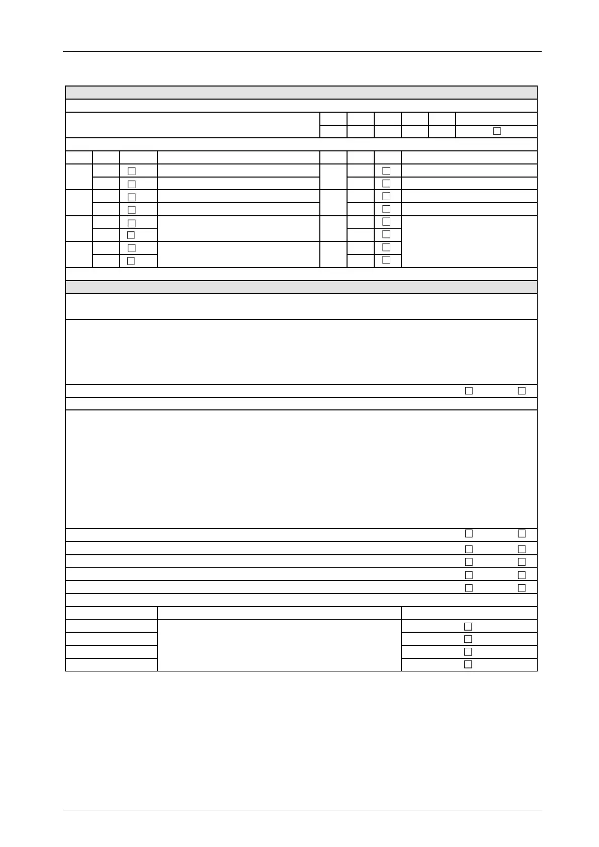
Set program 8 via DIP switches (check box as applicable)
Safety instruction: Before setting the DIP switches, disconnect the switch gear cabinet and Interface from the electrical supply.
DIP S1-1 S1-2 S1-3 S1-4
Pos. OFF OFF OFF ON
DIP Pos. Function DIP Pos. Function
OFF
Slave
OFF
Inoperative
ON
Master
ON
Forced mode
OFF
X4b: Compressor signal; X4c: Defrost signal
OFF
All digital outputs (NO)
ON
All digital outputs (NC)
OFF OFF
ON ON
OFF OFF
ON ON
Program 8: Set DIP switches for direct frequency request (check box as applicable)
SW4-3 on outdoor unit set to ON
Yes No
Thi-A sensor replaced by 5 kΩ fixed resistor
Cooling: Temperature setpoint set to 18 °C on wired remote control
Yes No
Heating: Temperature setpoint set to 30 °C on wired remote control
Yes No
On wired remote control: Setpoint temperature button disabled
Wired remote control disabled by signal to X2b-D3 Yes No
For setting the analog signal, see Set analog signal at analog input X3.
Description of the direct frequency request:
Adapts the Interface to the compressor frequency of the outdoor unit installed on site, as per Table 2.
Description of program 8:
Direct frequency request
Program 8 activated
S2-1
S2-2
S2-3
S2-4
S2-5
S2-6
S2-7
S2-8
To set the 7-segment display, see table:
7-segment display: Set DIP switches to
display frequency request.
Inoperative, DIP switch setting is always OFF
Inoperative, DIP switch setting is always OFF
For FDC outdoor units: Set DIP switch S1 on Interface
1. Set DIP switch SW4-3 on the outdoor unit PCB of the FDC outdoor unit to ON
(see Technical Manual of FDC series).
2. Identify which FDC outdoor unit is installed on site (see Table 2).
3. Set DIP switches S1-5 to S1-8 in line with the FDC outdoor unit installed on site (see Table 2).
For SRC outdoor units: Set DIP switch S1 on Interface
Make sure there is always a request during a setpoint/actual value comparison.
1. Replace the Thi-A sensor with a 5 kΩ fixed resistor (see Technical Manual for heat exchanger connection module).
2. Set the temperature setpoint on the wired remote control:
─ When using to cool: Set temperature setpoint to 18 °C.
─ When using to heat: Set temperature setpoint to 30 °C.
3. Disable the wired remote control so temperature setpoint cannot be changed.
─ Alternatively: Disable the wired remote control by means of a signal to digital input X2b-D3 (Interface = Center).
4. Identify which SRC outdoor unit is installed on site (see Table 2).
5. Set DIP switches S1-5 to S1-8 in line with the SRC outdoor unit installed on site (see Table 2).