CompTrol Interface V4.0.x | Issue 21-05-2021 | 1000932 43
Program 3 – temperature setpoint denition for equipment rooms with temperature limit alarm
13
12
1 2 3
4
98765
11
10
1415
16
17
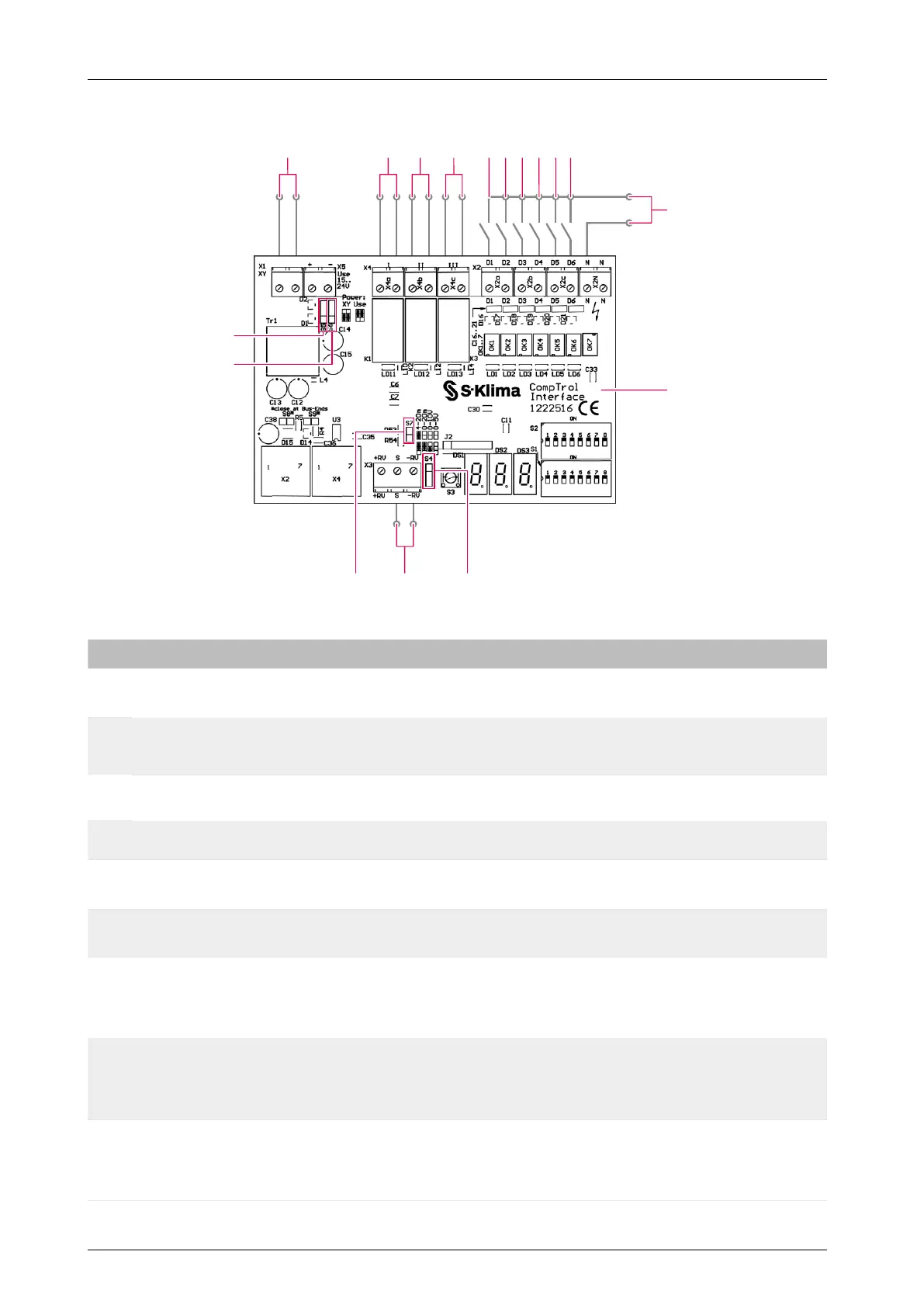
Figure 9: Connection diagram for program 3
No. Name No. Name
1 X/Y remote control bus 2
Digital outputs X4a-I
Alarm signal
3
Digital outputs X4b-II
(see “Table 28: Digital outputs in program 3”
on page 47)
4
Digital outputs X4c-III
Temperature limit alarm
5
Digital input X2a-D1
Remote ON/OFF
6
Digital input X2a-D2
Cooling mode
7
Digital input X2b-D3
Center/Center-Remote
8
Digital input X2b-D4
Evaluate analog input
9
Digital input X2c-D5
Fan speed F1; D5+D6 Fan speed F3
10
Digital input X2c-D6
Fan speed F2; D5+D6 Fan speed F3
11 Input voltage 24-230 V AC / 20-130 V DC 12 CompTrol Interface expansion module
13 Analog input X3-S, X3-(-RV) 14
Pin header S4 for setting the analog signal
type (analog input X3)
(see “Table 6: Analog signal type” on
page 19)
15
Pin header S7 for setting the analog signal
type (analog input X3)
(see “Table 6: Analog signal type” on
page 19)
16
Pin header S6 for setting the electrical
supply
(see “Table 5: Type of electrical supply” on
page 18)
17
Pin header S5 for setting the electrical
supply
(see “Table 5: Type of electrical supply” on
page 18)
- -