Cold Load Pickup Activated
Select the Enabled mode to congure the Cold Load Pickup modier settings.
Max Modifier – Percent of Minimum Trip/Low Current Cutoff
Percent of the Min Trip/Low Current Cutoff setpoint at which timing is inhibited.
Pickup and timing above this level will follow the congured inverse characteristics.
(Range: 100%-500%; Step: 1%; Default: 200%)
T1—Start Applying Modifier after Outage
This is the duration of the power outage (in minutes) when the modier is applied at its
minimum value. (Range: 1-600; Step: 1; Default: 15)
T2—Ramp to Full Modifier Value after T1
This is the time after T1 (in minutes) when the modier has ramped up to its maximum
value. (Range: 0-600; Step: 1; Default: 15)
T3—Start Ramping Modifier Down after Return
This is the duration of power restoration (in minutes) when the modier is ramped down
from its maximum value. (Range: 0-600; Step: 1; Default: 15)
T4—Modifier Completely Off after T3
This is the time after T3 (in minutes) when the modier is removed at its minimum value.
(Range: 1-600; Step: 1; Default: 15)
Viable Voltage Setting
This is the percentage of system phase-to-phase voltage at which the Cold Load Pickup
Timer starts. (Range: 5%-95%; Step: 1%; Default: 90%)
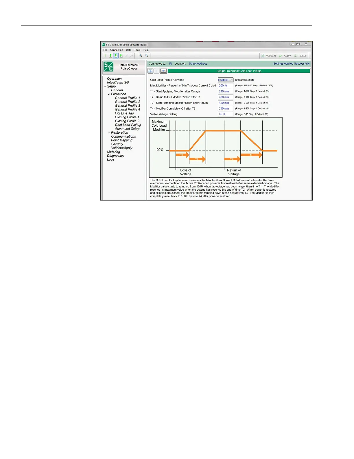
Figure 60. The Setup>Protection>Cold Load Pickup screen.
110 S&C Instruction Sheet 766-530
Protection Setup

 Loading...


