Vacuum Interrupter Leakage Detection Section
When the Yes option is chosen for the Leakage Current Error Check mode, after every
Open operation leakage current sensing is delayed by the Delay Before VI Leakage
Detection Enabled setpoint. Only current above the Current Level for VI Leakage
Detection setpoint is considered leakage current. The duration of leakage current at
each pole is totaled by the Leakage Current Denite Time Element Timers. At
60 Hz, one cycle = 16 ms. When the number of mlliseconds recorded by any of the Leakage
Current Denite Time Element Timers equals the number of cycles congured for
the Denite Time Delay setpoint, a VI Leakage Detection error is reported. When any
pole timer reaches 50% of the Denite Time Delay setpoint, an alarm is reported, and
at 80% of the Denite Time Delay setpoint, a warning is reported. When no VI leakage
current is detected for the duration of the Denite Time Element Reset Timer setpoint,
all Leakage Current Denite Time Element Timers are reset to 0.
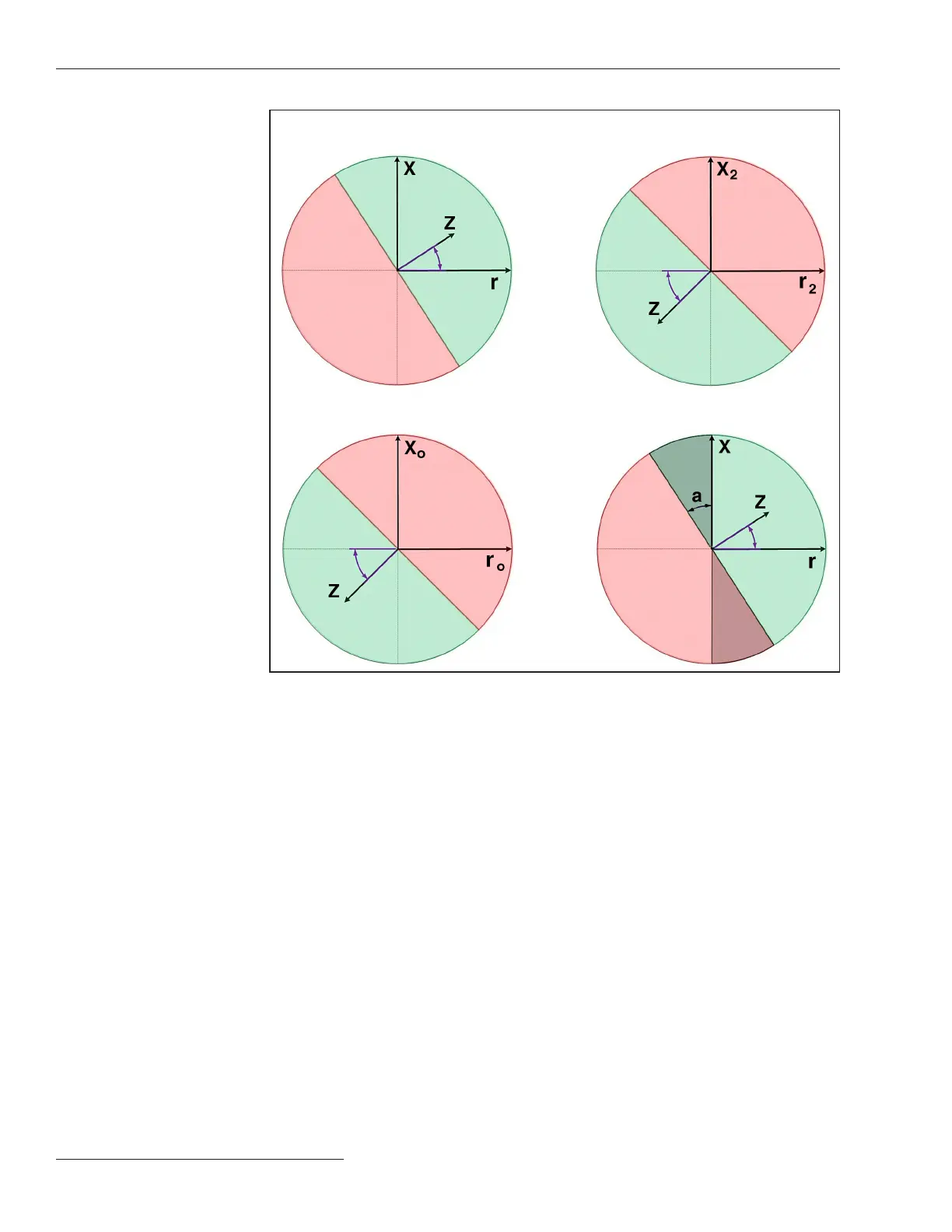
Figure 62. Default Reference Impedance (Z) Angle diagrams as plotted on their respective
resistance and reactance (r/x) planes, Direction X operating area is red, Direction Y operating
area is green. Note 1: Default Blocking Region for Direction Y (a= 33°). Note 2: Default
Blocking Region for Direction X.
Default
= 33°
Default
= 33°
Default
= 45°
Default
= 45°
Note
1
Note
2
Phase
Reference Impedance Angle
Negative Sequence
Reference Impedance Angle
Phase Reference Angle
Special Case (SLG Events)
Zero Sequence Reference Impedance
Angle Multigrounded
Direction X
Operating
Region
Direction X
Operating
Region
Direction X
Operating
Region
Direction X
Operating
Region
114 S&C Instruction Sheet 766-530
Protection Setup

 Loading...


