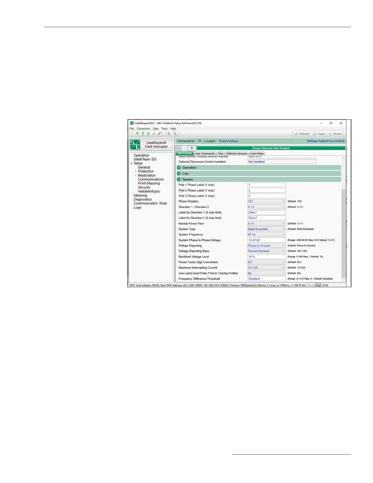
Figure 6. The Setup>General>Site-Related>System screen.
System Section
Pole 1 Phase Label (1 character)
This is the label for Pole 1. See Figure 6.
Pole 2 Phase Label (1 character)
This is the label for Pole 2.
Pole 3 Phase Label (1 character)
This is the label for Pole 3.
Information about Phase Rotation Settings
The IntelliRupter fault interrupter measures phase rotation (123, 132, or Undened)
using both terminal X & Y phase voltages. If viable voltage is present on both terminals,
only terminal X is used when determining phase rotation.
• When the IntelliRupter fault interrupter control powers up it may take sev-
eral minutes before the measured phase rotation is displayed on the Metering
screen. Until then, the Metering screen displays the phase rotation setting on the
Setup>General>System>Phase Rotation screen.
• Until terminal-X phase rotation is measured, the IntelliRupter fault interrupter
measures positive and negative sequence voltage based on the 123 or 132 setting in
Setup>General>System>Phase Rotation screen.
• In the event the phase rotation setting on the Setup>General>System>Phase
Rotation screen results in the IntelliRupter fault interrupter detecting both terminals
X & Y have higher negative sequence voltages than positive sequence voltages, the
Metering screen will initially display negative sequence voltages for both terminals.
After about 1 minute these terminal X & Y negative sequence voltages will change to
positive sequence voltages.
S&C Instruction Sheet 766-530 19
General Setup
 Loading...


