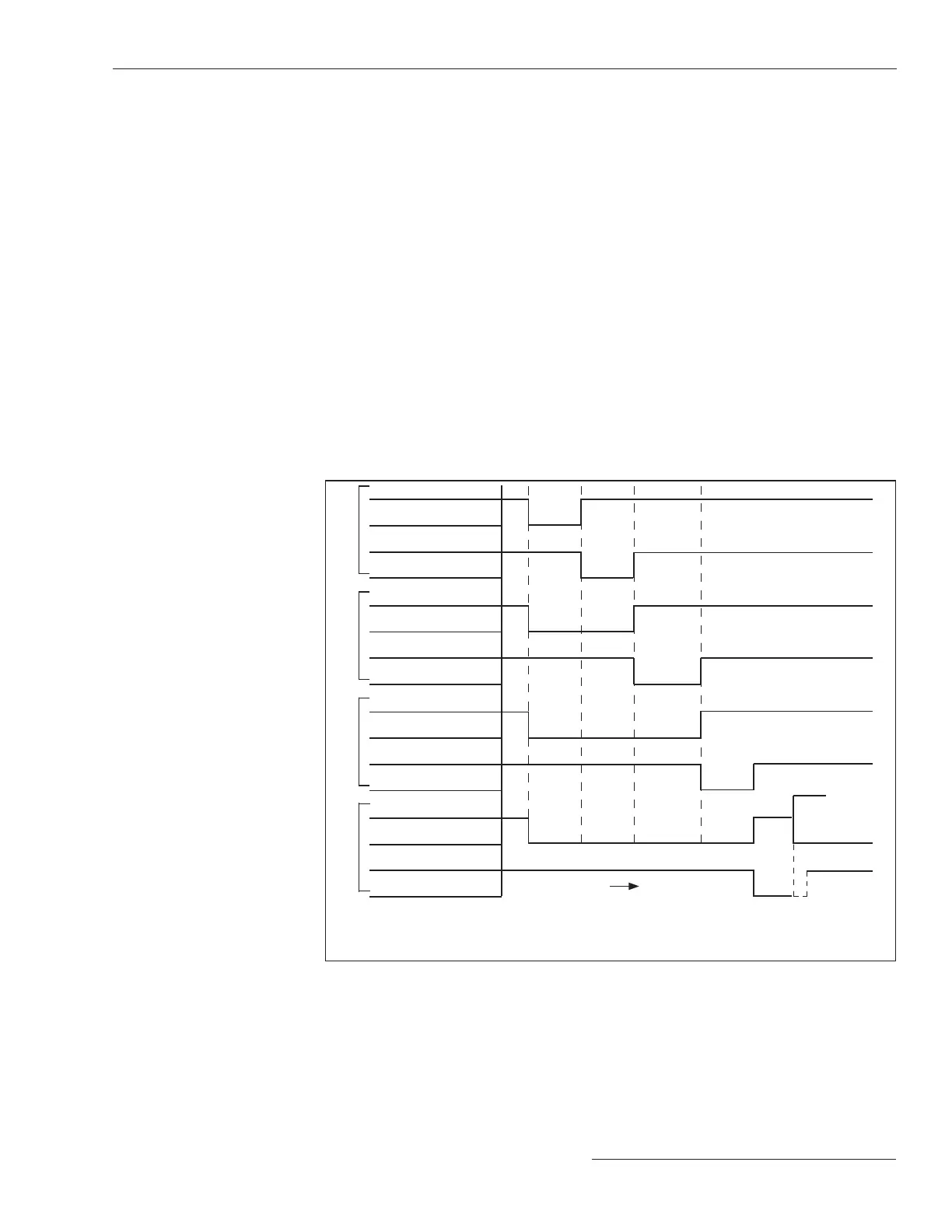
The timing diagram in Figure 39 shows the relationship between the Test-n Delay
Time setpoint on the Setup>Protection>General Profile n>Testing After Initial Trip
screen, the Test TCC Hold Time, and the Test Delay Time setpoints.
IR 4
IR 3
IR 2
IR 1
Closed
Open
P-TCC
Shift TCC
Closed
Open
P-TCC
Shift TCC
Closed
Open
P-TCC
Shift TCC
Closed
Open
P-TCC
Shift TCC
TnDT
TTHT
TnDT TDT
TTHT
TnDT No volt TDT
TTHT
TnDT No volt No volt
TDT
TTHT
Trip using
Shift TCC
time
Legend:
TnDT = Test-n Delay Time TTHT = Test TCC Hold Time
TDT = Test Delay Time
P-TCC = Previous TCC
Figure 39. The timing example for the PulseFinding technique with the TCC Shifting; the margin
setting is not accounted for.
Test Delay Time
This is the amount of time testing is delayed after the Good Source Voltage Indication
threshold has been met. This time applies to all test sequences. (Range: 0.3-300.1;
Step: 0.1; Default: 0.9)
Trip on Test Sequence TCC Low Cutoff
(Applies to both directions for this profile)
When checked, the TCC Shifting function performs an instantaneous trip whenever
the fault current reaches the Minimum Trip Level setting of any congured element
for the active Test Sequence TCCs before the Test TCC Hold Time setting expires.
The For Close Operations and the For Pulse Operations settings (see Figure 38 on
page 54) are all valid for the Trip on Test Sequence TCC Minimum Pickup function.
The Low Current Cutoff of the resulting TCC is the Instantaneous Trip Level setting
for the Test TCC Hold Time setting. When the Low Current Cutoff of the resulting TCC
is set to “N/A,” the Minimum Trip Level of the resulting TCC becomes the Instantaneous
Trip Level.
S&C Instruction Sheet 766-530 55
Protection Setup
 Loading...


