Hardware manual PCD7.LRxx-PG5 room controller │ Document 27-653; version ENG07 │ 2019-03-21
Saia-Burgess Controls AG
RS-485 signal level
Appendix
A-3
A
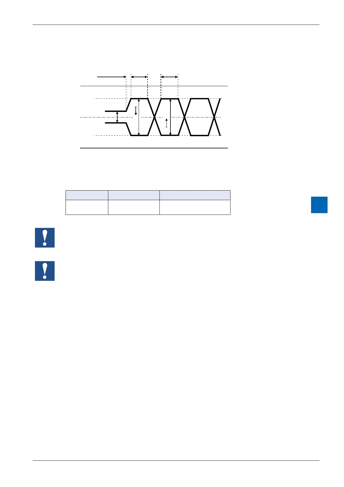
A.2 RS-485 signal level
VOH
VOL
not active
e.g. start bit
mark space
5 V
2.5 V
0 V
4 V
3 V
2 V
1 V
VOZ
/TX
TX
VOZ = 0.9 V min.
VOH = 1.5 V min. (with load) … 3.6 V max. (without load)
VOL = -1.5 V min. (with load) … -3.6 V max. (without load)
Signal type Logical status Polarity
Data signal 0 (blank)
1(symbol)
RX-TX positive at /RX-/TX
/RX-/TX positive at RX-TX
lines.
In order to ensure problem-free operation of an RS-485 network, the network should be connected
at both ends. Cables and terminating resistors should be selected in accordance with manual 26-

 Loading...

