Hardware manual PCD7.LRxx-PG5 room controller │ Document 27-653; version ENG07 │ 2019-03-21
Saia-Burgess Controls AG Communication
5
5-15
Modbus on PCD7.LRxx-P5 RS-485 interfaces
5.4.2 Addressing
Coils
using the same address.
-
dress.
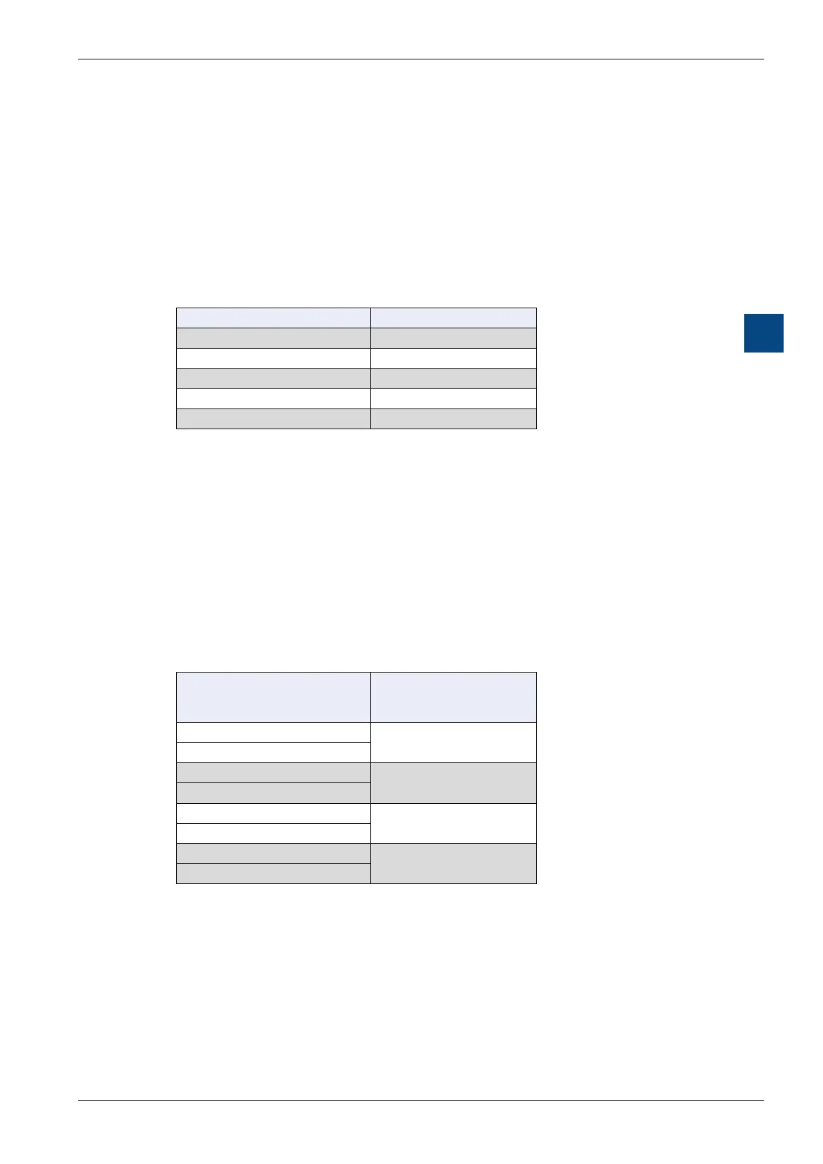
Modbus coils (C0..C4040) are mapped to PCD Flags (F0..F4040)
Modbus Coils Address PCD Flags Address
C0 F0
C1 F1
C2 F2
… …
C4040 F4040
Holding Registers
The media register area is seen by Modbus as an array of 16-bit holding registers.
As the size of the media registers (used internally by the PCD) is 32 bits and Mod-
bus uses only 16-bit registers, 2 Modbus holding registers are needed for each
PCD register:
Modbus Holding Registers (HR0..HR8051) are mapped to
PCD Register (R0..R4025)
Modbus
Holding Registers Address
(16 bits)
PCD
Media Registers Address
(32 bits)
HR0
R0
HR1
HR2
R1
HR3
…
…
…
HR8050
R4025
HR8051
If the Modbus master supports 32-bit read/write, it is easier to use.
When reading or writing media registers with Modbus, the main point is that you
need to multiply the register address by 2.

 Loading...

