Hardware manual PCD7.LRxx-PG5 room controller │ Document 27-653; version ENG07 │ 2019-03-21
Saia-Burgess Controls AG
Dimensions/device installation
Room controller/CPU
3-5
3
3. Push the slide lock(s) back into the initial position until another audible click is
heard.
Ensure that the PCD7.LRxx-P5 is hooked in correctly and is locked into place.
The room controller can then be wired.
If installing vertically on a DIN rail, the device must be secured from slipping using
a stop.
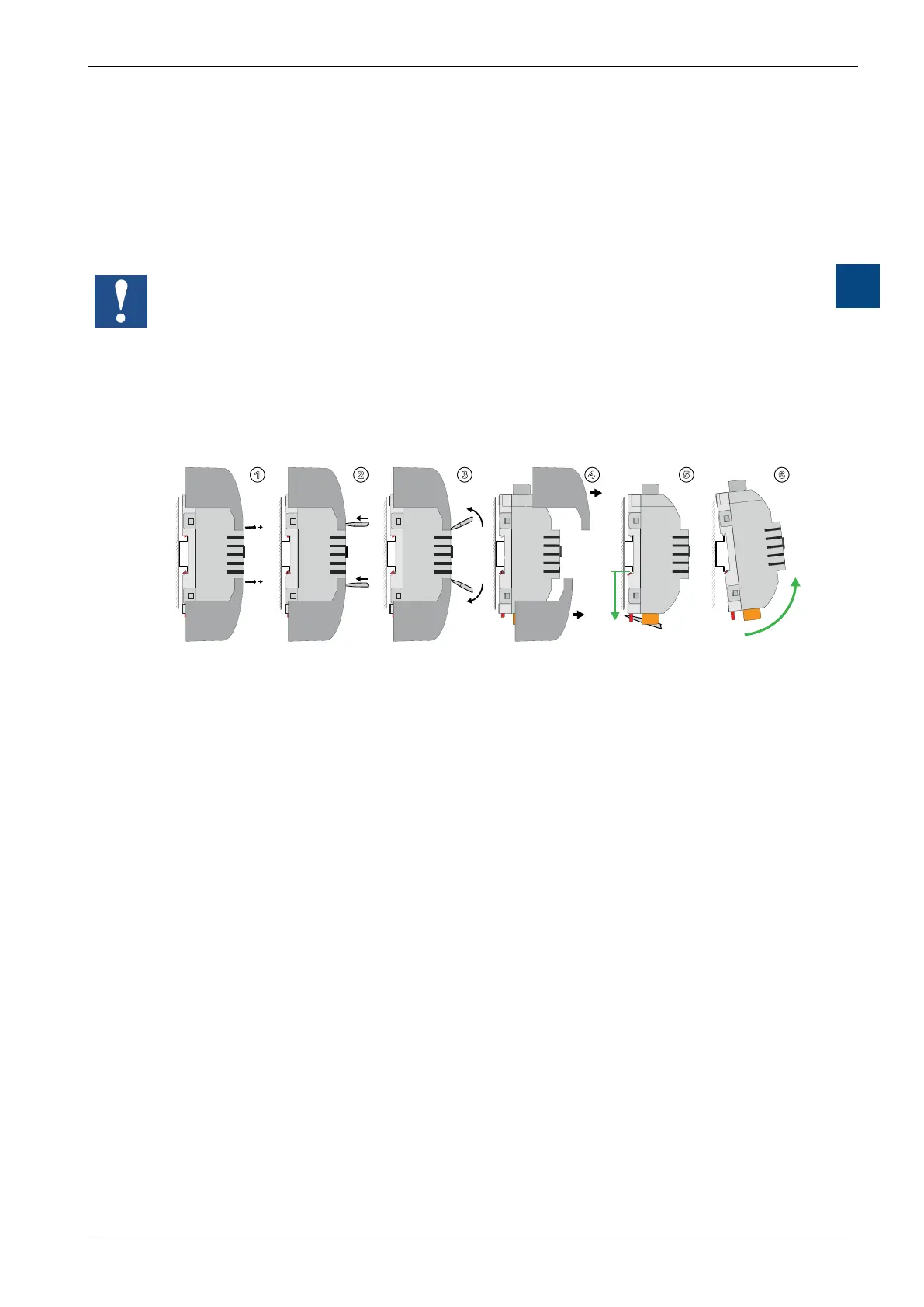
3.1.5 Removal from mounting rails
1. Remove the fastening screws on the protective terminal covers and use a slot-
ted screwdriver to disengage the lock at the points marked with arrows.
2. Remove the two protective terminal covers individually and vertically from the
device.
3. Label the connection wiring.
Remove all wired connectors.
4. Use a slotted screwdriver, for example, to push back or move the slide lock(s)
on the bottom
of the PCD7.LRxx-P5 until an audible click is heard.
5. Lift the bottom part of the room controller from the bottom edge of the mounting
rail (pull it out approx. 5 mm) and raise it over the top edge of the mounting rail.
Remove the room controller.
Push the two slide locks back into the initial position until an audible click is
heard again.

 Loading...

