Hardware manual PCD7.LRxx-PG5 room controller │ Document 27-653; version ENG07 │ 2019-03-21
Saia-Burgess Controls AG
Dimensions/device installation
Room controller/CPU
3-6
3
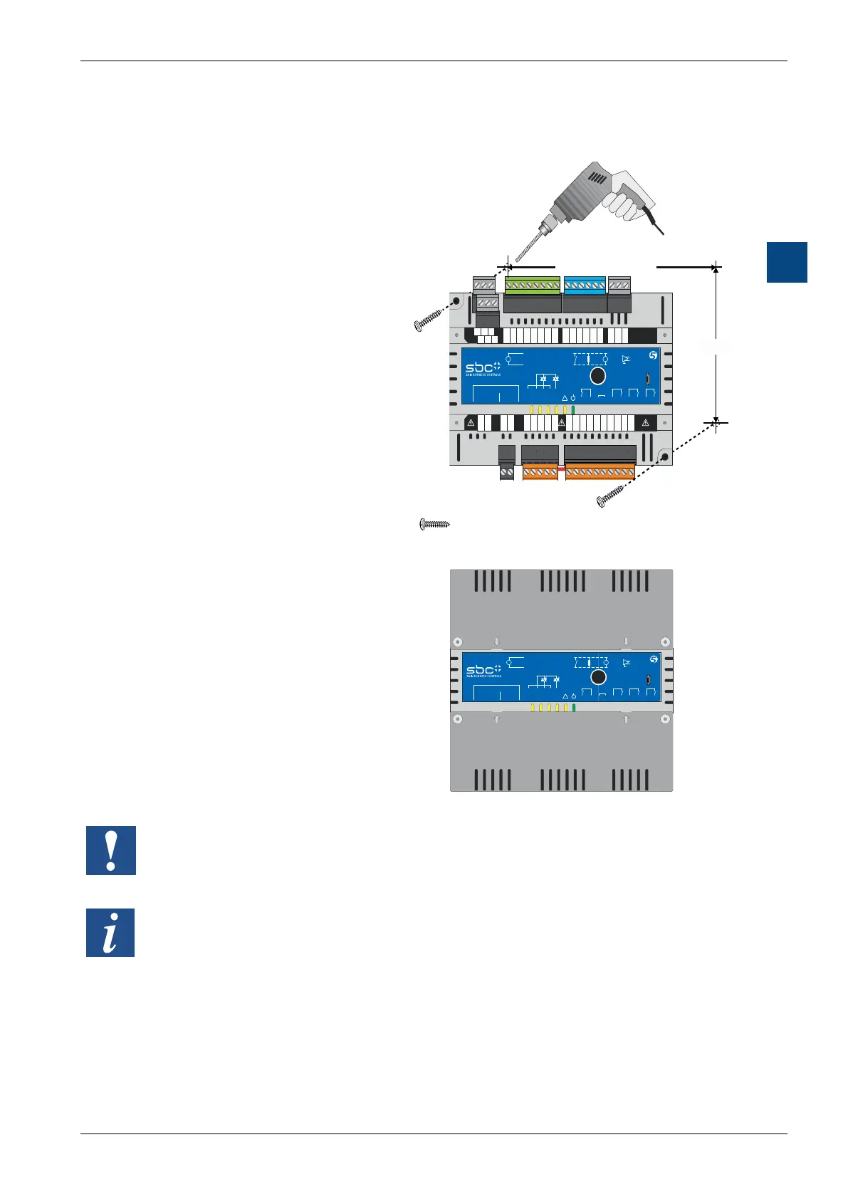
3.1.6 Wall mounting
The device can be mounted on any
even surface in any desired posi-
tion. (See also section “Ambient
for temperature range restrictions
ceiling.)
The device is installed by inserting
optional screws through the corre-
sponding screw holes.
= DIN EN ISO 7049 – ST4,2x22 – C – H
AO0…
GND
0-10V
V
UI0…
0-10 V
GND
Dig. NTC
V
RS485 / Port 0
/D A +
D B -
RO3 IN3 RN RN IN0 RO0 IN1 RO1 IN2 RO2
TN T~ TO0 TN TO1
RUN/HALT
Power Supply
---
230 V In
24 VAC In
24 VAC Out
Sylk Bus
RS485 / Port 1
USB
T1 R1 T0 R0
!
1
L
2
N
3
24V~
4
24V0
5
TN
6
T~
7
TO0
8
TN
9
TO1
10
RO3
11
IN3
12
RN
13
RN
14
IN0
15
RO0
16
IN1
17
RO1
18
IN2
19
RO2
AO0
26
24V~
27
GND
28
AO1
29
AO2
30
24V~
31
UI0
34
GND
35
UI1
36
/DA+
40
DB-
41
GND
42
UI2
37
GND
38
UI3
39
GND
32
AO3
33
WM1
20
WM2
21
24V~
22
/DA+
23
DB-
24
GND
25
3 4 5 6 7 8 9 10 11 12 13 14 15 16 17 18 19
40 41 4226 27 28 29 30 31 32 33 34 35 36 37 38 39
20 21 22
23 24 25
99.5
LRLx-P5: 187.5
LRSx-P5: 151.5
After mounting the device on the
wall, the protective terminal covers
optionally available for the device
(see Fig. 3) should be installed.
AO0…
GND
0-10V
V
UI0…
0-10 V
GND
Dig. NTC
V
RS485 / Port 0
/D A +
D B -
RO3 IN3 RN RN IN0 RO0 IN1 RO1 IN2 RO2
TN T~ TO0 TN TO1
RUN/HALT
Power Supply
---
230 V In
24 VAC In
24 VAC Out
Sylk Bus
RS485 / Port 1
USB
T1 R1 T0 R0
!
If mounting on a wall, the otherwise optional protective terminal covers
The covers can be secured using optional screws as per DIN EN ISO 7049 –
ST2.9x9.5 - C (F) - H (not included in scope of supply).
3.1.7 Removal from the wall
Follow the instructions in reverse order to remove.

 Loading...

