Hardware manual PCD7.LRxx-PG5 room controller │ Document 27-653; version ENG07 │ 2019-03-21
Saia-Burgess Controls AG Communication
5
5-11
RS-485 interfaces (ports 0 + 1) in general
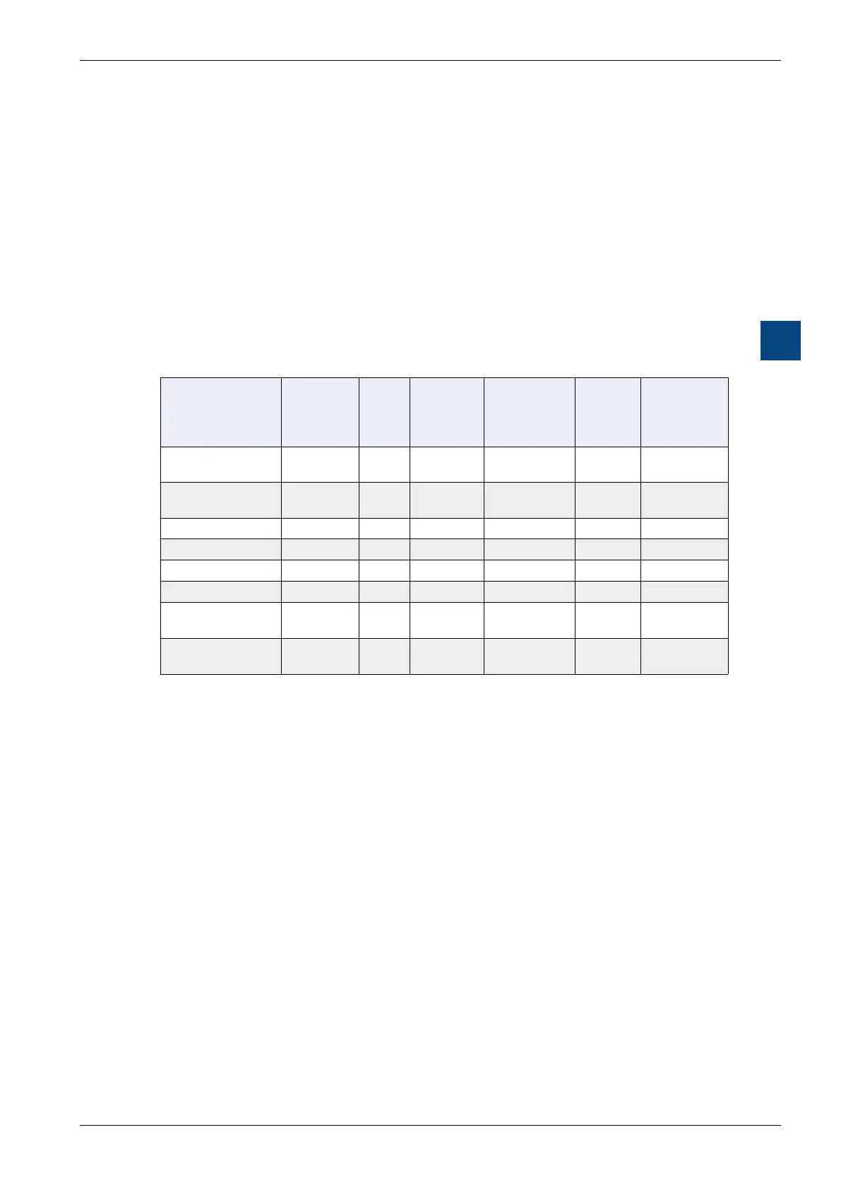
Example 2:
What is the resource requirement for a network with a PCD7.LRxx-P5 room
controller with four HVAC room template applications (for four zones):
4 HVAC (for
four
zone) room template application
1 PCD7.LRxx-P5 room controller
1 PCD1.E1000-A10 digital inputs
1 PCD1.A1000-A20 digital outputs
1 PCD1.G2000-A20 digital/analogue inputs and outputs
3 PCD1.B5000-A20 digital/analogue inputs and outputs
E-Line FBoxes Registers Flags Program
size
Size of RAM
data blocks
DB RAM Non-
volatile
data
(inash)
[Byte] [Byte] [Flags or
registers]
4 HVAC
room templates
1700 1400 70444 866
EL + S-Bus master 196 119 2188 2064 2
3 PCD1.B5000
111 216 17196 336 3
1 PCD1.G2000
70 58 8708 200 1
1 PCD1.A1000
54 124 7012 168 1
Necessary
resources
2131 1917 105548 2768 7 866
% usage of
PCD7.LRxx-P5
53% 48% 82% 28% 7% 87%
be the program size, where only approximately 14 kB of the user program is left
5.3.5.3 Recommendations for use with lighting or blind control
When switching lighting or blind outputs, the response times should not be more
than 250 ms so that a switching command will not be perceived as delayed.
The following points must be observed to achieve this:
S-Bus/Modbus setting 115 kbit/s
only E-Line modules on second RS-485 (e.g. no energy counters)
no more than four E-Line modules on the second RS-485
disable the manual operating level for E-Line modules
the user program must not be too big so that the PCD7.LRxx-P5 room control-
ler can still process at least 14 cycles per second. This can be achieved with a

 Loading...

