Hardware manual PCD7.LRxx-PG5 room controller │ Document 27-653; version ENG07 │ 2019-03-21
Saia-Burgess Controls AG Communication
5
5-23
Sylk bus
5.5 Sylk bus
AO0…
GND
0-10V
V
UI0…
0-10V
GND
Dig. NTC
V
RS485 / Port 0
/D A +
D B -
RO3 IN3 RN RN IN0 RO0 IN1 RO1 IN2 RO2
TN T~ TO0 TN TO1
RUN/HALT
Power Supply
---
230 V In
24 VAC In
24 VAC Out
Sylk Bus
RS485 / Port 1
USB
T1 R1 T0 R0
!
1
L
2
N
3
24V~
4
24V0
5
TN
6
T~
7
TO0
8
TN
9
TO1
10
RO3
11
IN3
12
RN
13
RN
14
IN0
15
RO0
16
IN1
17
RO1
18
IN2
19
RO2
AO0
26
24V~
27
GND
28
AO1
29
AO2
30
24V~
31
UI0
34
GND
35
UI1
36
/DA+
40
DB-
41
GND
42
UI2
37
GND
38
UI3
39
GND
32
AO3
33
WM1
20
WM2
21
24V~
22
/DA+
23
DB-
24
GND
25
1 2
3 4 5 6 7 8 9 10 11 12 13 14 15 16 17 18 19
40
41
4226 27 28 29 30 31 32
33
34
35
36
37
38
392021 22
23 24 25
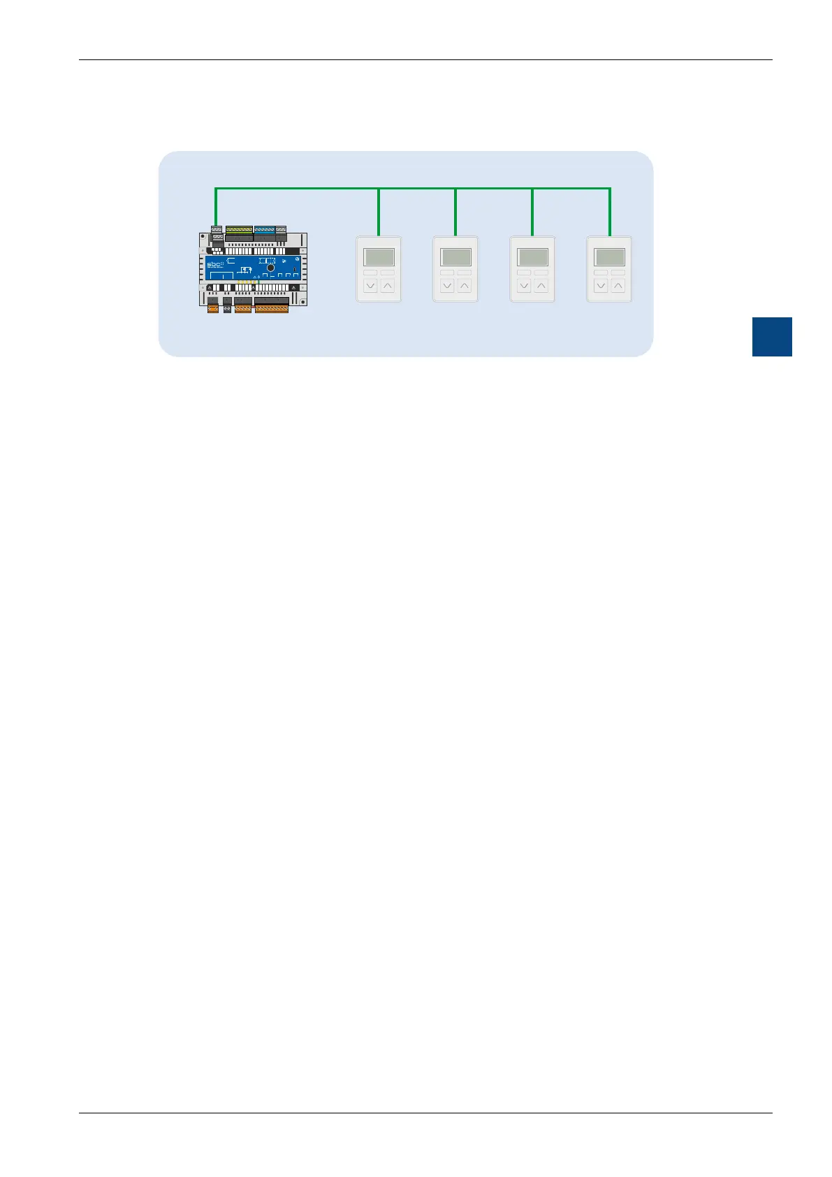
Sylk-Bus
PCD7.RLxx-P5
S S S
M
S
Room control
5.5.1 Key information about the bus
Two-wire bus; polarity can be reversed
Sylk™ bus cable length up to 150 m
Communication and power supply via the same wires
Multiple devices, such as room operating devices
- PCD7.LR-TR4x,
- PCD7.LR-TR4x-H,
- PCD7.LR-TR4x-CO2,
- PCD7.LR-TR4x-H-CO2
Up to 4 Sylk bus devices on the same bus

 Loading...

