Hardware manual PCD7.LRxx-PG5 room controller │ Document 27-653; version ENG07 │ 2019-03-21
Saia-Burgess Controls AG
RUN/HALT key
Room controller/CPU
3-18
3
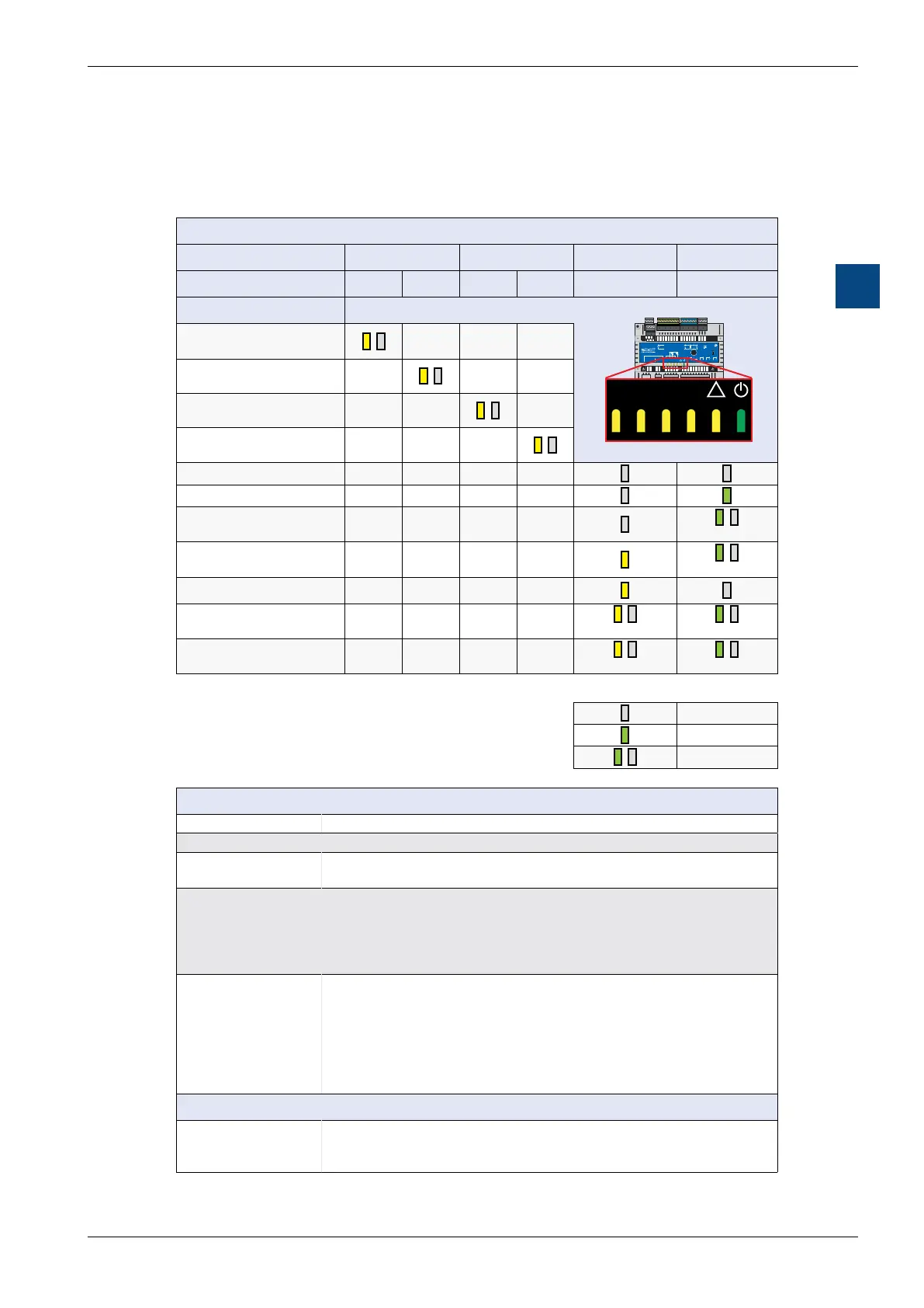
3.9 LED/operating states
The colour LEDs indicate the possible operating statuses of the CPU, as shown in
the following table.
Meaning of LEDs
Function Com Port #1 Com Port #0 STOP/HALT RUN
Labelling T1 R1 T0 R0
Description
AO0…
GND
0-10V
V
UI0…
0-10V
GND
Dig. NTC
V
RS485 / Port 0
/DA +
DB -
RO3 IN3 RN RN IN0 RO0 IN1 RO1 IN2 RO2
TN T~ TO0 TN TO1
RUN/HALT
Power Supply
---
230 V In
24 VAC In
24 VAC Out
USB
Sylk Bus
RS485 / Port 1
T1 R1 T0 R0
!
1
L
2
N
3
24V~
4
24V0
5
TN
6
T~
7
TO0
8
TN
9
TO1
10
RO3
11
IN3
12
RN
13
RN
14
IN0
15
RO0
16
IN1
17
RO1
18
IN2
19
RO2
AO0
26
24V~
27
GND
28
AO1
29
AO2
30
24V~
31
UI0
34
GND
35
UI1
36
/DA+
40
DB-
41
GND
42
UI2
37
GND
38
UI3
39
GND
32
AO3
33
WM1
20
WM2
21
24V~
22
/DA+
23
DB-
24
GND
25
3 4 5 6 7 8 9 10 11 12 1314 15 16 17 18 19
40 41 4226 27 28 29 30 31 3233 34 35 36 37 38 39
20 21 22
23 24 25
Data transfer via
RS-485 interface #1
/
– – –
Data receipt via
RS-485 interface #1
–
/
– –
Data transfer via
RS-485 interface #0
– –
/
–
Data receipt via
RS-485 interface #0
– – –
/
– – – –
RUN (program running) – – – –
RUN Until (program running) – – – –
/
STOP
(no program running)
– – – –
/
HALT
(no program running)
– – – –
FW download – – – –
/
/
RESET/service key pressed – – – –
/
/
Legend:
LED off
LED on
/
LED flashing
Operating status
Start Self-diagnostics for approx. 1 s after power-on or restart
Run Normal processing of user program after start
Run Until Conditional run status. A condition has been set in the debugger
that has not yet been met
Stop -
- Programming unit connected in PGU mode while the CPU
was switched on
- PGU stopped by programming unit
-
HALT -
- RUN/HALT key pressed
- HALT instruction processed
- Critical error in user program
- Hardware error
- No program loaded
- No communication mode with S-Bus PGU or gateway master port
System diagnostics
Reset - The RESET status is caused by the following:
- Supply voltage too low
- Firmware not started

 Loading...

