Hardware manual PCD7.LRxx-PG5 room controller │ Document 27-653; version ENG07 │ 2019-03-21
Saia-Burgess Controls AG
Digital outputs
Inputs/outputs (I/O)
4-17
4
Property Type 1
(standard)
Type 2
(high switch-on current)
PCD7
LRLx-P5
PCD7.
LRSx-P5
Electrical endurance
70,000 cycles
4 A at 250 VAC
100,000 cycles
10 A at 250 VAC
yes yes
Application Fan motor, light
Switching of light, fan motor
and electrical heater
yes yes
If inductive components are connected to the relays and these relays switch more
than once every two minutes, these components must not cause any harmful
interference to radio or TV reception (conformity with EN 45014).
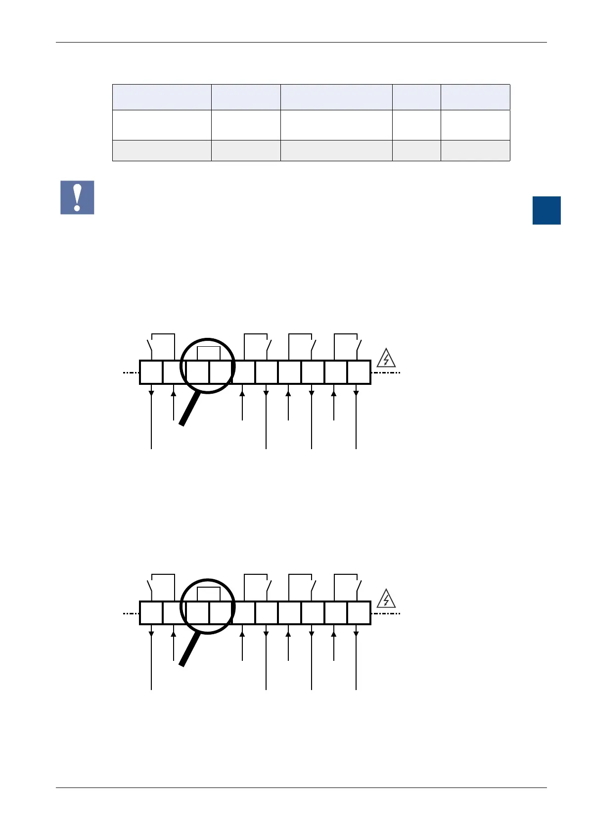
Connection schematic:
PCD7.LRLx-P5
RO3
IN3 RN RN IN0
RO0
IN1
RO1 IN2 RO2
16
17 18 19 20
21
22
23 24 25
RN = Reserve
terminals serve
as distributors
OUTPUTS - RELAYS
max. 10 A
15…253 V AC
max. 4 A
15…253 V AC
max. 4 A
15…253 V AC
max. 10 A
15…253 V AC
PCD7.LRSx-P5
RN = Reserve
terminals serve
as distributors
OUTPUTS - RELAYS
max. 10 A
24…253 V AC
max. 4 A
15…253 V AC
max. 4 A
15…253 V AC
max. 4 A
15…253 V AC
RO3
IN3 RN RN IN0
RO0
IN1
RO1 IN2 RO2
10
11 12 13 14
15
16
17 18 19

 Loading...

