Hardware manual PCD7.LRxx-PG5 room controller │ Document 27-653; version ENG07 │ 2019-03-21
Saia-Burgess Controls AG
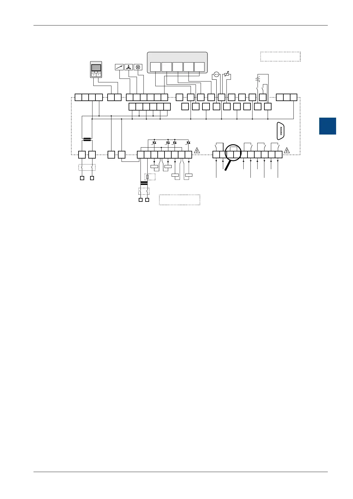
Connection examples
Inputs/outputs (I/O)
4-24
4
V
PCD7.LRL4-P5 / PCD7.LRL5-P5
LN
230 VAC
TEMP SETUP FAN
Q.RCU-A-TSOF
WALL MODULE
PCD7.LR-TR42
room operating devices
* OPTIONAL FUSE (TO PROTECT THE
CONTROLLER‘S INTERNAL TRANSFORMER,
WHICH HAS ONLY A NON-RESETTABLE FUSE).
RS-485
Port 1
RS-485
Port 0
! Note grounding concept !
see „27-653 Manual IRM-PG5“
max. 1.25 A
slow blow (IEC)
RN = Reserve
terminals serve
as distributors
digital
analog
OUTPUTS
analog
OUTPUTS - RELAYS
max. 10 A
15…253 V AC
OUTPUTS - TRIACS
max. 4 A
15…253 V AC
max. 4 A
15…253 V AC
max. 10 A
15…253 V AC
UNIVERSAL INPUTS
24
VDC
1 2 3 4 5
F1*
TN
T~ TN
TO1 TO2
TN
TO3
L N
TO0
24 V~ 24 V0
7
8 10
11 12
13
14
9
47
UI0
49 51
UI3
53
UI4
55
57
UI7
59
UI8
61
45
LED
44
46
48
UI1
50
UI2
52 54
UI5
56
UI6
58
60
UI9
RO3
IN3 RN RN IN0
RO0
IN1
RO1 IN2 RO2
16
17 18 19 20
21
22
23 24 25
32
AO0
34
AO1
36
AO2
38
AO3
40
AO4
42
AO5
30
WM1
31
WM2
39 43
37 41
35
33
24 V~ 24 V~ 24 V~
NL
LED
5 6
1 2
Micro-USB
/DA+ DB-
/DA+ DB-
63 6462
24 V~
29
24 V~
27 2826
Sylk
Bus
GND GNDGND
GND
GND GND GND
GND
GND
GNDGND
GND
230 V AC
24 V~24 V0
Example wiring PCD7.LRL4-P5 / PCD7.LRL5-P5 with wall module Q-RCU-A-TSOF
(eg: LED at terminal 42).

 Loading...

