3.9.3
Flag Indicator / Output Relays Settings (DiggiMEC)
Depending on the ordered type, the DiggiMEC features either one ag indicator FI2, or three
ag indicators FI1, FI2, FI3.
See also ╚═▷ “3.9.2 DiggiMEC Connectors”.
Each of these ag indicators is mechanically coupled with a bistable output relay. At any
time, the WIC1 can toggle the state of an FIx. Note that each FIx is always only set with the
rising edge of the assigned signal.
With respect to the DiggiMEC ag indicators, there is the following convention: In the state
appearing as a red-colored mark at the DiggiMEC front the ag indicator / output relay has
been “set”, and the other state means that the FIx has been “reset”.
WARNING!
A CT-powered WIC1 is able to reliably set and reset the ag indicators only under the
condition that it is supplied with sucient electrical energy via the CTs. (Unfortunately
the required electrical energy depends on various aspects, e. g. how many ag indicators
shall be switched at the same time, or whether the impulse outputs shall be triggered,
too. Therefore it is impossible to explicitly specify any limit value.)
CAUTION!
It is not possible for the WIC1 to check the current state of any FIx. So, if the user
mechanically changes the state of an FIx the new state is not signaled to the WIC1.
In other words: Although it is possible at any time to change the state of an FIx by
hand, this should only be done with great care, being aware of potential consequences,
because this also switches the state of the output relay contacts.
After a reset (via HMI or Digital Input), however, all FIx – regardless whether with
or without latching – (re-)assume their correct states according to the current state
of the assigned signals. (Important: The reset is functional only if the WIC1 settings
have specied which DiggiMEC variant is connected; the related parameter is [Device
planning / WIC1 + DiggiMEC] »DiggiMEC . Mode«.)
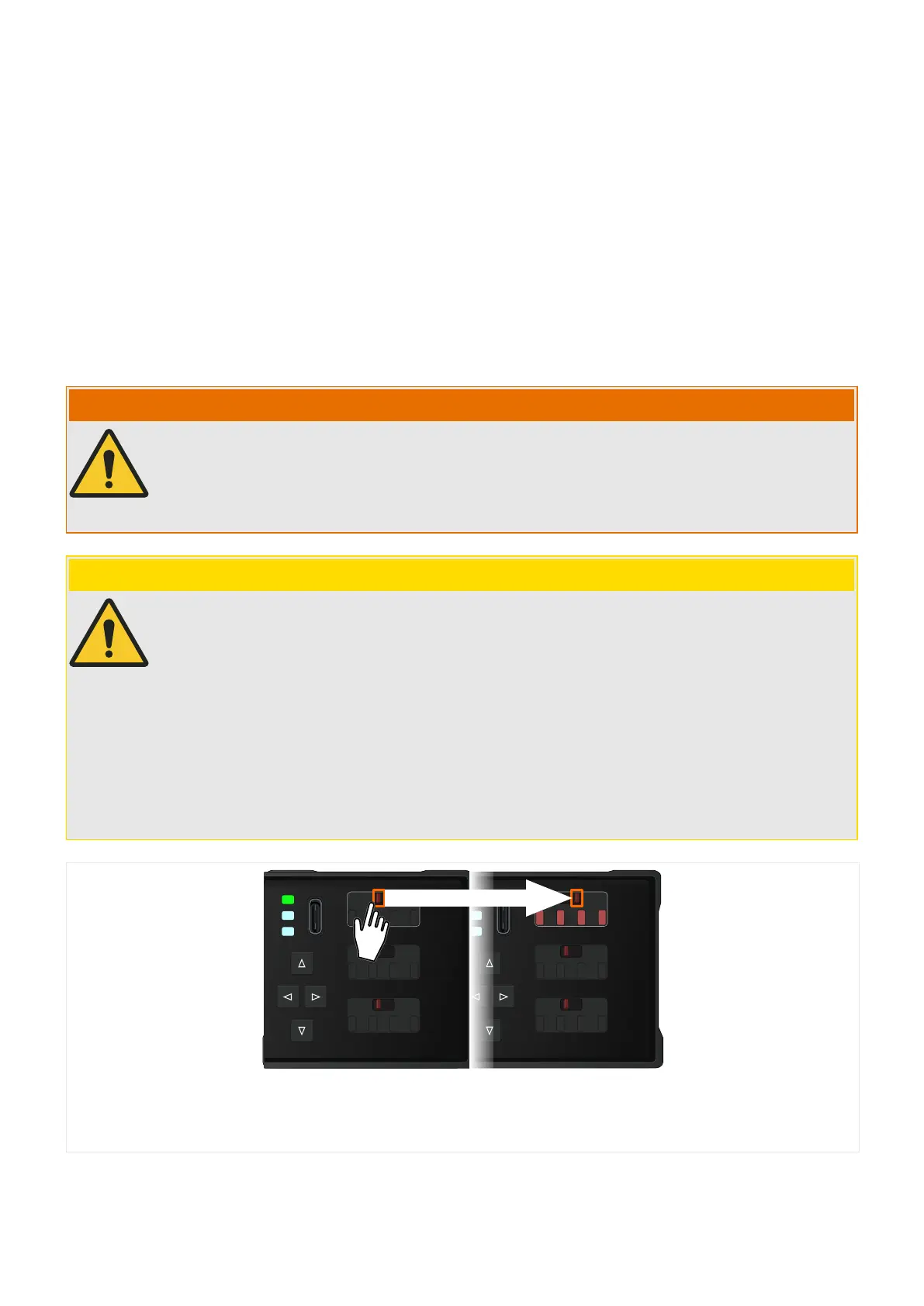
Fig. 38: Important: Manually toggling the state of a ag indicator also switches the contacts of the
respective output relay.
The conditions of a module output or signal of a protective function can be assigned to an
FIx, so that it is both electrically available (via the relay contacts) and visualized (via the ag
119WIC1WIC1-1.0-EN-MAN
3 Hardware
3.9.3 Flag Indicator / Output Relays Settings (DiggiMEC)
 Loading...


