EasyManuals Logo

Sega UFO CATCHER User Manual

Sega UFO CATCHER
131 pages
To Next Page IconTo Next Page
To Previous Page IconTo Previous Page
Page #31 background imageLoading...
Page #31 background image
24
GAME BOARD
10
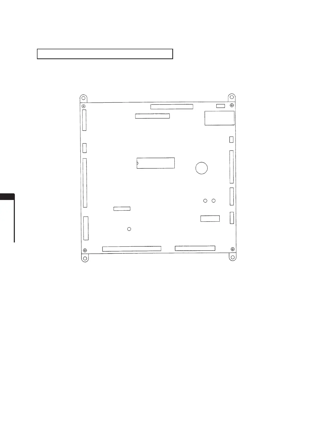
GAME BOARD CONFIGURATION DIAGRAM
The DIP SWs on the game board are not used for game settings but must all be set to OFF.
GAME BD UCU V2: 834-14760
[CN1 (JST RA34P)]: Switch, Analog Input
[CN2 (JST RA50P)]: Switch, Sensor Input
[CN3 (JST RA16P)]: Power Supply Input
[CN4 (JST NH25P)]: Lamp, Catch Motor Output
[CN5 (JST NH12P)]: Ticket Output
[CN7 (JST RA40P)]: Meter, AC Motor Output
[CN8 (JST NH4P)]: Speaker Output
[CN9 (JST NH3P)]: Sound Volume Input
[CN10 (JST NH16P)]: 7-seg Display Output
[CN11 (JST NH10P)]: 7-seg Display Output
[CN12 (JST NH6P)]: Not used.
[CN14 (JST NH8P)]: Not used.
[CN15 (JST NH5P)]: DIPSW BD Signal
CONNECTORS AND INPUT/OUTPUT
FIG. 10
CN7
CN8
NH4P
CN9
NH3P
CN18
NH16P
CN11
NH18P
LED2 LED1
DIPSW
RA34PRA50P
CN1CN2
CN12
NH6P
CN3
RA16P
CN14
NH8P
POWER LED (This is lit when powering on.)
CN4
NH25P
CN15
NH5P
CN5
NH12P
RA40P
HEAT SINK
834-14760
ROM

Questions and Answers:

Question and Answer IconNeed help?

Do you have a question about the Sega UFO CATCHER and is the answer not in the manual?

Sega UFO CATCHER Specifications

General IconGeneral
BrandSega
ModelUFO CATCHER
CategoryArcade Game Machines
LanguageEnglish

Related product manuals