MX-M700N ADJUSTMENTS 6 – 25
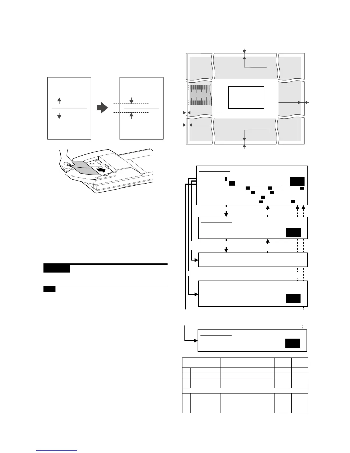
(Scan off-center adjustment)
1) Place an original on the DSPF original tray.
2) Press the Start key.
Since the front side and back side images are copied onto sep-
arate sheets, check the off-center of the back side image.
If the off-center is 0r2.7 mm, no adjustment is required.
If the above requirement is not met, do the following steps.
3) Using the numeric keypad, change the adjustment value in
steps of 0.1 mm to adjust the scan image off-center. A larger
setting shifts the printed image toward the rear side.
4) Press the P or Start key.
Pressing the Start key starts copy operation as well as apply-
ing the adjustment value.
5) Check the off-center of the printed image.
Repeat the above adjustments until an acceptable result is
obtained.
ADJ 8 Adjusting the image position,
image loss, and void area
8-A Adjust copied image loss/void area in
original table mode
This adjustment is needed in the following situations:
* The paper feed section has been disassembled.
* The MFP control PWB has been replaced.
* The EEPROM on the MFP control PWB has been replaced.
* The scan control PWB has been replaced.
* The EEPROM on the scan control PWB has been replaced.
* The scanner (reading) section has been disassembled.
* The scanner (reading) unit has been replaced.
* The LSU has been replaced.
* U2 trouble has occurred.
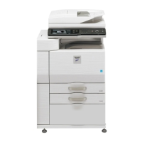
1) Go through the modes specified in Simulation 50-1.
original copy
a
b
Select 2, and press
[START] key.
Press [START] key, or press
[SYSTEM SETTINGS] key.
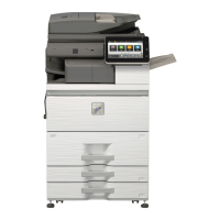
Item Content
Setting
range
Default
0 TRAY SELECT Paper feed tray selection 1 – 6 –
1 COPY START Copy START (Default) – –
2 MAGNIFICATI
ON
Print magnification ratio 25 –
400%
–
(Lead edge adjustment value)
3 RRCA Document scan start position
adjustment value
0 – 99 50
4 RRCB Resist roller clutch ON timing
adjustment value
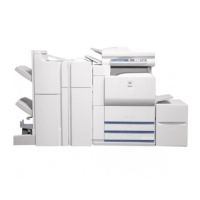
Image loss (LIL)
LIL = 1.5 mm
LV = 3.5 mm
TV = 3.5 mm
FV+RV
= 7.0 mm
Papar lead edge Papar tail edge
10 20
No Image
No Image
No Image
No Image
Void (TV)
Void (LV)
Void (FV)
Void (RV)
50
1
2
SIMULATION 50-1
LEAD EDGE ADJUSTMENT. INPUT VALUE 0-99, AND PRESS
START.
3.RRCA
SIMULATION 50-1
LEAD EDGE ADJUSTMENT. NOW COPYING.
SIMULATION 50-1
LEAD EDGE ADJUSTMENT. SELECT 1-6, AND PRESS START.
(FEED TRAY)
1.TRAY1 2.TRAY2 3.TRAY3 4.TRAY4
5.BPT 6.LCC
SIMULATION 50-1
LEAD EDGE ADJUSTMENT. SELECT 0-9, AND PRESS START.
0.TRAY SELECT 1 1.COPY START
2.MAGNIFICATION 100
(ADJUSTMENT DATA) 3.RRCA 50 4.RRCB 50 10.SIDE2 ADJ. 50
(IMAGE LOSS SETTING) 5.LEAD 15 6.SIDE 20
(VOID SETTING) 7.LEAD_EDGE(DENA) 50
8.TRAIL_EDGE(DENB) 30 9.FRONT/REAR 30
Select other than0-2,and
press [START] key.
Press [SYSTEM SETTINGS] key.
Select 1, and
press [START] key.
Press [START] key.
Press [SYSTEM SETTING] key,
or terminate copying.
Select 0, and press [START] key.
Press [START] key,
or press [SYSTEM SETTINGS] key.
100
SIMULATION 50-1
LEAD EDGE ADJUSTMENT.
(MAGNIFICATION)
INPUT 25-400(%)