SERVICE MANUAL
Parts marked with " " are important for maintaining the safety of the set. Be sure to replace these parts with
specified ones for maintaining the safety and performance of the set.
This document has been published to be used
for after sales service only.
The contents are subject to change without notice.
SHARP CORPORATION
NOTE FOR SERVICING
[1] PRODUCT OUTLINE . . . . . . . . . . . 1-1
[2] SPECIFICATIONS . . . . . . . . . . . . . 2-1
[3] CONSUMABLE PARTS . . . . . . . . . 3-1
[4] UNPACKING AND INSTALLATION
*
For unpacking and installation, refer to
the installation manual (00ZAR700//I1E).
[5] EXTERNAL VIEW AND INTERNAL
STRUCTURE . . . . . . . . . . . . . . . . . 5-1
[6] ADJUSTMENTS . . . . . . . . . . . . . . . 6-1
[7] SIMULATION . . . . . . . . . . . . . . . . . 7-1
[8]
SELF DIAG AND TROUBLE CODE
.8-1
[9] MAINTENANCE . . . . . . . . . . . . . . . 9-1
[10] ROM VERSION-UP . . . . . . . . . . . .10-1
[11] ELECTRICAL SECTION. . . . . . . . . 11-1
[12] OTHERS. . . . . . . . . . . . . . . . . . . . .12-1
● DETAILS OF EACH SECTION
[A] EXTERNAL OUTFIT . . . . . . . . . . . . A-1
[B] OPERATION PANEL . . . . . . . . . . . B -1
[C] DSPF SECTION . . . . . . . . . . . . . . . C -1
[D] SCANNER SECTION . . . . . . . . . . . D-1
[E]
MANUAL PAPER FEED SECTION
. . E-1
[F] TRAY PAPER FEED SECTION . . . F -1
[G] PAPER TRANSPORT SECTION . . G -1
[H] DUPLEX SECTION . . . . . . . . . . . . H -1
[ i ] LSU SECTION . . . . . . . . . . . . . . . . i -1
[J] PHOTOCONDUCTOR SECTION. . J -1
[K] TONER SUPPLY SECTION . . . . . . K -1
[L] DEVELOPING SECTION . . . . . . . . L -1
[M] TRANSFER SECTION . . . . . . . . . . M-1
[N] FUSING SECTION . . . . . . . . . . . . . N -1
[O] PAPER EXIT SECTION . . . . . . . . . O -1
[P] DRIVE SECTION . . . . . . . . . . . . . . P -1
[Q] PWB SECTION. . . . . . . . . . . . . . . . Q -1
[R] FAN AND FILTER SECTION . . . . . R -1
[S] SENSOR, SWITCH SECTION . . . . S -1
CODE: 00ZMXM700/S2E
CONTENTS
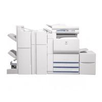
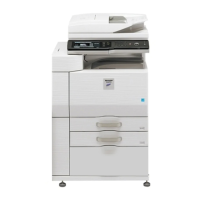
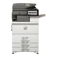
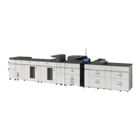
MX-M550N/M550U
MX-M620N/M620U
MX-M700N/M700U
DIGITAL MULTIFUNCTIONAL
SYSTEM
MODEL