Parameter Description
Parameter Description
119
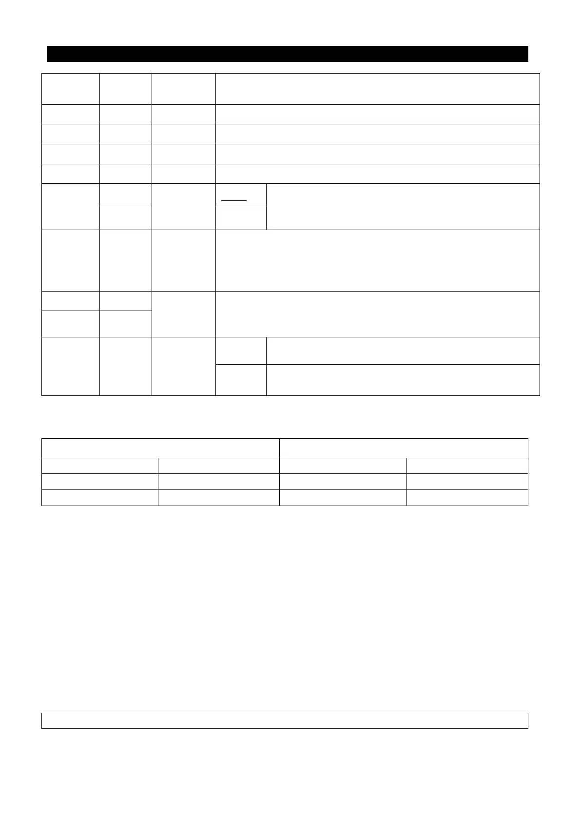
Parameter
Factory
Setting
Setting
Range
Remarks
178 0 0~100% ---
179 1s 0~255s ---
180 90% 0~100% ---
181 40Hz 0~120Hz ---
182
50 Hz
0~120Hz
P.189=1
When the deviation value accumulated with the integral
time, an upper limit for deviation accumulation should
be set.
60Hz P.189=0
183 0.5Hz 0~10Hz
When the feedback pressure satisfies the deviation value for
stopping the machine and the set time (in seconds) for stopping
the machine for detection is reached, the inverter will take the
P.183 step to reduce the frequency.
223 0%
0~100%
Revising the feedback signal to unify the signal range of inverter’s
feedback terminal and actual feedback, so that the inverter display
in accordance with the feedback meter.
224 100%
225 20%
0~100%,
9999
0~100%
The target value is set by P.225.
9999
When P170=1, 4-5 current/voltage set the target value;
When P170=2, 2-5 voltage set the target value.
• The revising instruction of the analog feedback bias pressure and gain pressure:
1. The following system default value can be used without revising again:
The feedback of terminal 2-5 The feedback of terminal 4-5
Revising voltage Revising proportion
Revising current Revising proportion
0.1V P.223 4mA P.223
5V P.224 20mA P.224
Note: The range of default setting is 0.1~5V. If there is a mismatch between the default setting range
and the user’s range, P.223 and P.224 can be set and P.170 must be set at last to unify the range.
Example: When the 0~7V feedback signal is given by terminal 2-5:
1). When P.171=0 (negative feedback control), P.223 = 0.1 / 7 * 100.0 = 1.4
P.224 = 5 / 7 * 100.0 = 71.4
2). When P.171=1 (positive feedback control), P.223 = (7 - 0.1) / 7 * 100.0 = 98.6
P.224 = (7- 5) / 7 * 100.0 = 28.6
Example: When the 0~20mA feedback signal is given by terminal 4-5 (P.17=0, please make sure
that the switch AVI/ACI is switched to ACI):
1). When P.171=0 (negative feedback control), P.223 = 4 / 20 * 100.0 = 20.0
P.224 = 20 / 20 * 100.0 = 100.0
2). When P.171=1 (positive feedback control), P.223 = (20 – 4) / 20 * 100.0 = 80.0
P.224 = (20 – 20) / 20 * 100.0 =0
Note: If the feedback signal is given by the voltage of terminal 4-5, P.17 must be set firstly before above operation.

 Loading...