24
6.2 Operations
(1) Turn the power to the controller ON.
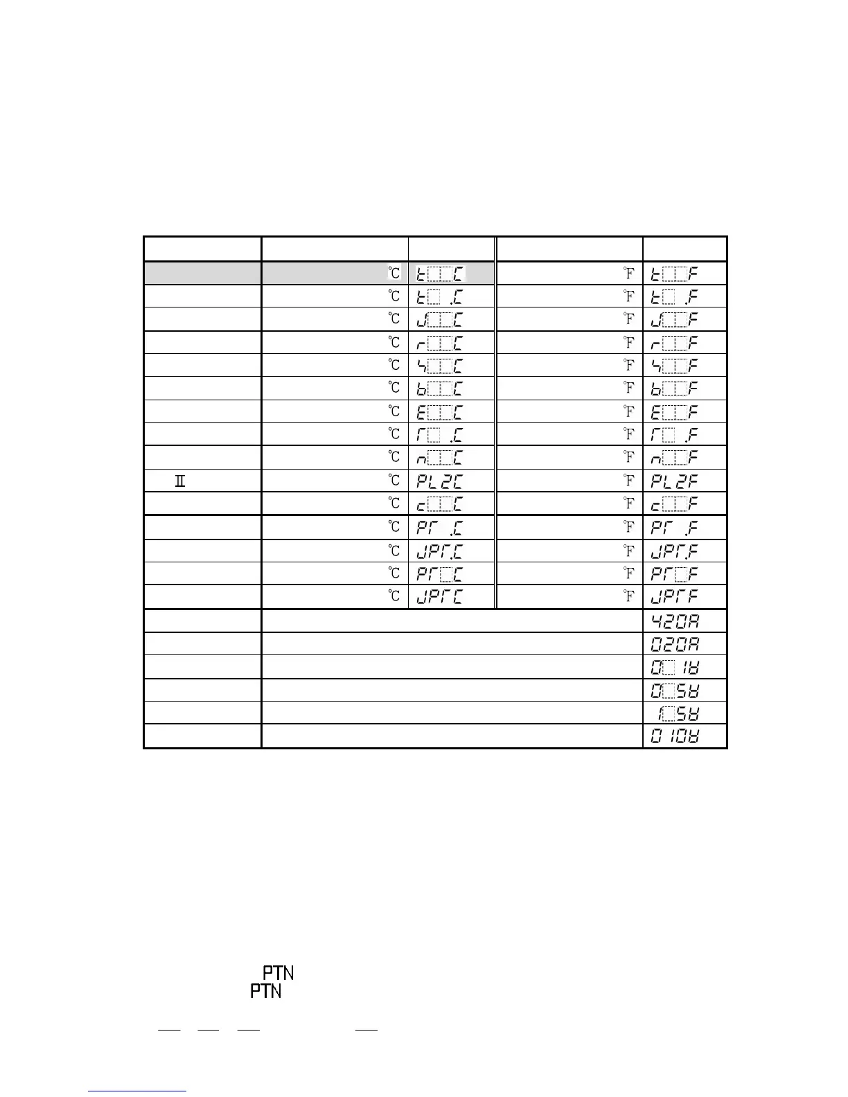
The sensor input character and temperature unit are indicated on the PV display and
the input range high limit value is indicated on the SV display for approx. 3 seconds
after the power is turned on. See (Table 6.2-1).
During this time, all outputs and the LED indicators are in off status.
After that, the controller switches to program standby mode.
(Table 6.2-1)
Input Scale range
Character
Scale range
Character
K -200 to 1370
4 to 20mA DC -1999 to 9999
0 to 20mA DC -1999 to 9999
0 to 1V DC -1999 to 9999
0 to 5V DC -1999 to 9999
1 to 5V DC -1999 to 9999
0 to 10V DC -1999 to 9999
(2) Program standby mode
This is a program standby mode. Therefore the control is not performed during this
mode.
In this mode, the currently selected pattern number is indicated on the PTN display and
actual temperature is indicated on the PV display.
(3) Program pattern number selection
Select a program pattern number before initiating various program settings.
The program pattern number can only be selected during the program standby mode.
It cannot be selected during program control run.
By pressing the key, select a program pattern number (1 to 9).
Each time the key is pressed, the program pattern number changes according
to the following.
1 2 3 4 ……….. 9 1