49
Alarm indicator and Alarm output
For A2 output, use terminals 12 and 13.
A1 and A2 indicators light when their terminals are connected, and go out when
their terminals are disconnected respectively.
When Alarm 1 (A1) Deenergized or Alarm 2 (A2) Deenergized is selected, the alarm
output ON/OFF status acts reversely. In this case, A1 and A2 indicators light when their
terminals are disconnected, and go out when their terminals are connected
respectively.
Alarm action in overscale and underscale
During overscale, High limit alarm, High/Low limits alarm and Process high alarm
are activated.
During underscale, Low limit alarm, High/Low limits alarm and Process low alarm
are activated.
For the alarm with standby function, the standby function is released.
9. Other functions
Power failure countermeasure
The setting data is backed up in the non-volatile IC memory.
If power failure occurs during the program control run, and if the power failure is
restored, the program control resumes from the point at which power failure occurred.
If power failure occurs during the fixed value control, and if the power failure is
restored, the fixed value control resumes.
Self-diagnosis
The CPU is monitored by a watchdog timer, and when any abnormal status is found on
the CPU, the indicator is switched to warm-up status.
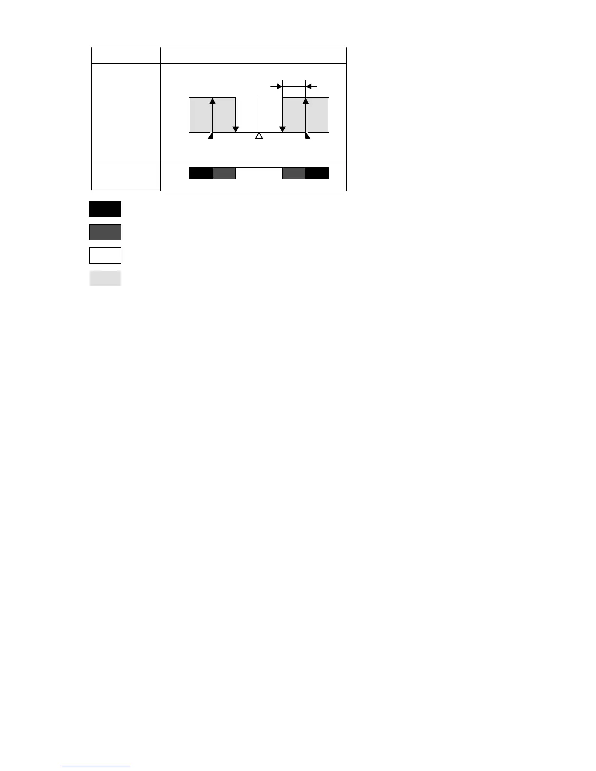
OFF
ON
High/Low limits alarm with standby
SV setting
A1
set point
A1
set point
Alarm action
Alarm output
A1 hysteresis
: A1 output terminals 7 and 8 are connected (ON).
: Standby functions.
:
:
A1 output terminals 7 and 8 are disconnected (OFF).
A1 output terminals 7 and 8 are connected (ON) or disconnected (OFF).