7
2 Name and functions of the sections
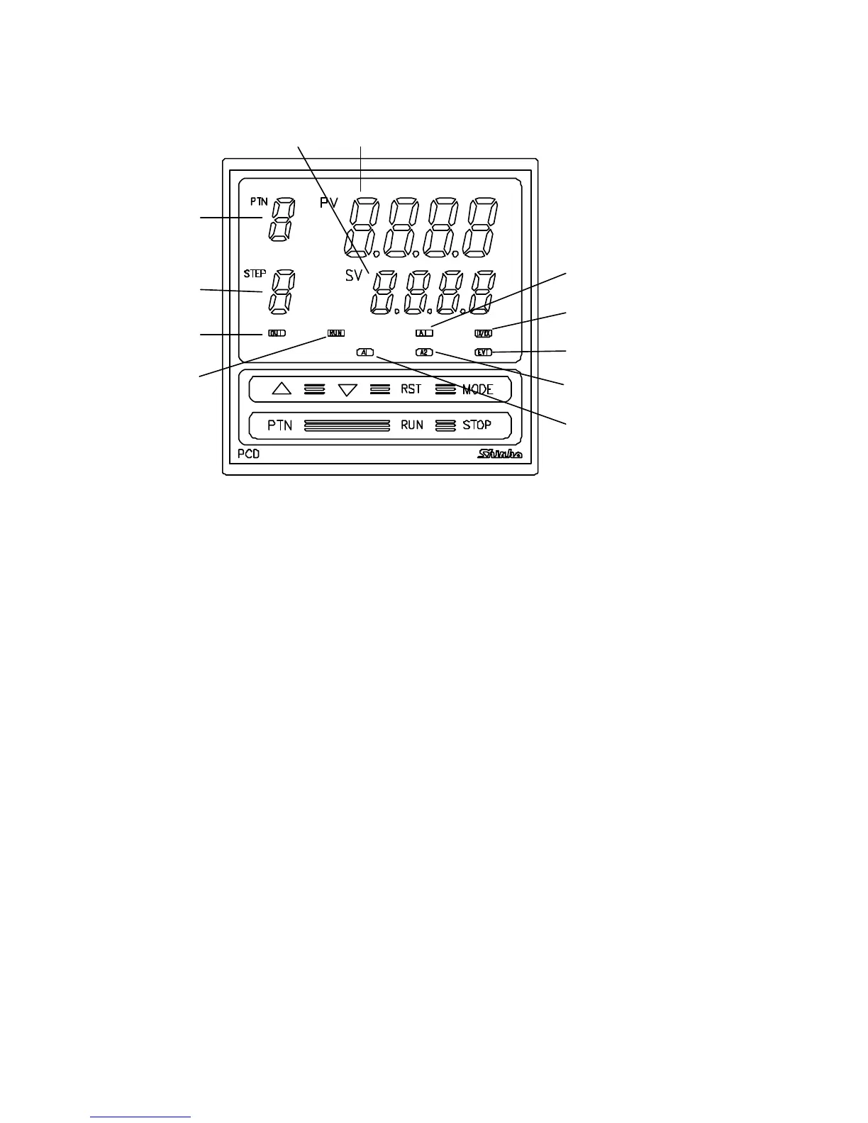
2.1 Name and Displays
(Fig. 2.1-1)
(1) PV display (Red)
Indicates the Process variable (PV).
When the setting mode is indicated, the setting item is indicated.
(2) SV display (Green)
Indicates the Setting value (SV).
When the setting mode is indicated, the setting value is indicated.
(3) PTN display (Green)
Indicates the Pattern number.
(4) STEP display (Green)
Indicates the step number.
While Wait function is working, the related step number blinks.
(5) OUT indicator (Green)
Lights when the control output is on.
(For the current output type, it blinks at a cycle of every 0.25 second
corresponding to the output manipulated variable.)
(6) RUN indicator (Red)
Lights while program control is performing.
Blinks while program control is held.
(7) A1 indicator (Red)
Lights when Alarm 1 (A1) output is on.
(8) A2 indicator (Red)
Lights when Alarm 2 (A2) output is on.
(9) EVT indicator (Red)
Lights when a selected output type from the Time signal output, Pattern
end output and Run output is on.
(10) TX/RX indicator (yellow)
Blinks while transmitting data in the Serial communication.
(11) AT indicator (yellow)
Blinks while auto-tuning is being performed.
(1)
(2)
(3)
(4)
(5)
(11)
(10)
(9)
(8)
(7)
(6)