22 GM32 · Technical information · 8011923 · V 1.4 · © SICK AG
CAN Connection
Subject to change without notice
3.1 GM32 CAN connection
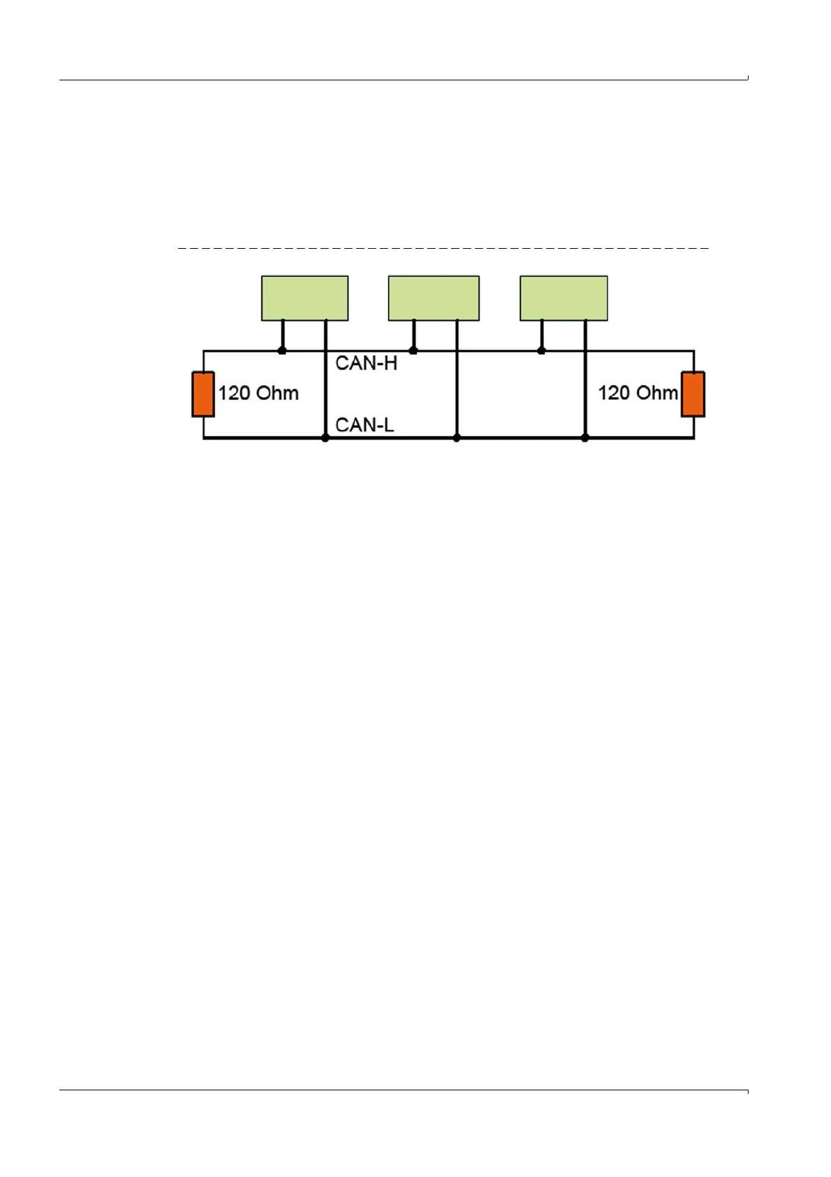
The CAN bus is a 2-wire bus system to which all bus participants are connected parallel
(i.e. with short stub lines).
● Each end of the CAN bus must be closed off with a 120 ±10% Ohm terminating resistor
(prevents reflections).
This is also required for very short line lengths.
Fig. 6 CAN bus principle
Terminating resistors must be activated for first and last bus participants.
The terminating resistor must be deactivated for middle bus participants.
GM32 default value:
– Probe: Resistor activated (last participant of a stub line)
– Gateway: Resistor activated (last participant).
The LED in the gateway is on.
Activating or deactivating terminating resistors Operating Instructions of bus partici-
pants.
For GM32:
p. 24, §3.3 and Operating Instructions “Modular System I/O”.
Stub lines lead to reflections on the bus, therefore:
Avoid stub lines whenever possible, otherwise limit these to max. 10 m.
CAN wiring:
Maximum length of the CAN bus: 1000 m
Cable twisted in pairs and shielded
– Surge impedance: 120 Ohm
– Capacitance: 60 pF/m.
Connect the shield across the complete bus and only ground galvanically at one loca-
tion (prevents ground loops).
First
participant
Middle
participant
Last
participant

 Loading...


