34 GM32 · Technical information · 8011923 · V 1.4 · © SICK AG
Operation (Specialist Menus)
Subject to change without notice
4.2.3 Parameters
4.2.3.1 Device parameters
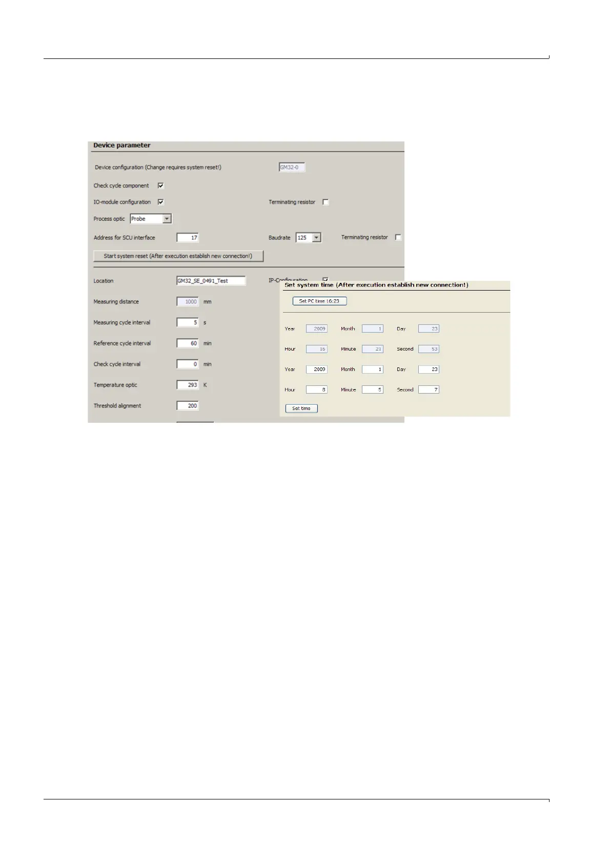
Menu: GM32/Parameter/Device parameter
● Check cycle component: Checkmark: Check cycle component installed.
● I/O module configuration: Checkmark: I/O module installed.
● Terminating resistor (for the CAN bus to the I/O modules):
– Checkmark set: Terminating resistor will be fitted (physically).
– Checkmark not set: No terminating resistor fitted.
● Process optic :
- No device: Probe installed without CAN bus
- Probe: Probe installed with CAN bus
- CD: Cross Duct version
● Address for SCU interface
● Baud rate
● Terminating resistor (for CAN interface to SCU):
– Checkmark set: Terminating resistor will be fitted (physically).
– Checkmark not set: No terminating resistor fitted.
● Location designation.
● IP-Configuration (checkmark): IP address change allowed / not allowed.
● Address for SCU interface (only when SCU used): Default: 17.
● Measuring distance: Active measuring path. The measuring path is read in from the
probe via the CAN bus).
● Measuring cycle interval: Default: 5 s.
● Reference cycle interval: Interval for the reference cycle.
Default 60 min. (change only possible for user level “Service”).
● Check cycle interval: Interval for the check cycle.
0 min. means: Switched off (change only possible for user level “Service”).

 Loading...