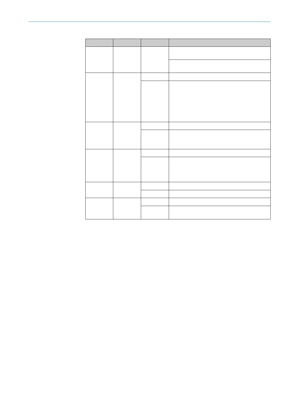
Table 2: Meaning of LEDs
Position LED Display Comment
!
OUT
O Gr
een
O Red
LED lights up green when protective field is free
(O
SSD on).
LED lights up red when protective field is inter‐
rupted (OSSD off).
"
EDM
O Or
ange
External device monitoring configured.
Ö Or
ange
For the configuration of EDM at the first OSSD sta‐
t
us change, the safety light curtain expects the
change from 24 V to 0 V at the multifunctional
input.
Or:
In combination with the ERR-LED Ö red: External
device monitoring reports defective contactor
§
COM
O W
hite
External communication active (e.g. for service)
Ö W
hite
No optical communication to another twin stick .
Or:
F
eedback when deactivating configuration.
$
RES
O Or
ange
Reset configured.
Ö Or
ange
Reset configured.
Or:
In combina
tion with ERR-LED Ö red and EDM-LED
Ö orange: error with configuration or cabling.
%
ERR
O Red
Protective field interrupted.
Ö R
ed
Error.
&
1, 2, 3, 4, 5
O Blue
Indication of the alignment quality.
Ö Blue In combination with ERR-LED Ö r
ed: display of an
error.
o LED of
f. Ö LED flashes. O LED illuminates.
Further topics
•
"Dia
gnostic LEDs", page 83
•
"Status indicators", page 17
•
"Aligning the twin sticks to one another", page 75
3 P
RODUCT DESCRIPTION
18
O P E R A T I N G I N S T R U C T I O N S | miniTwin4 8012624/10OM/2018-08-09 | SICK
Subject to change without notice