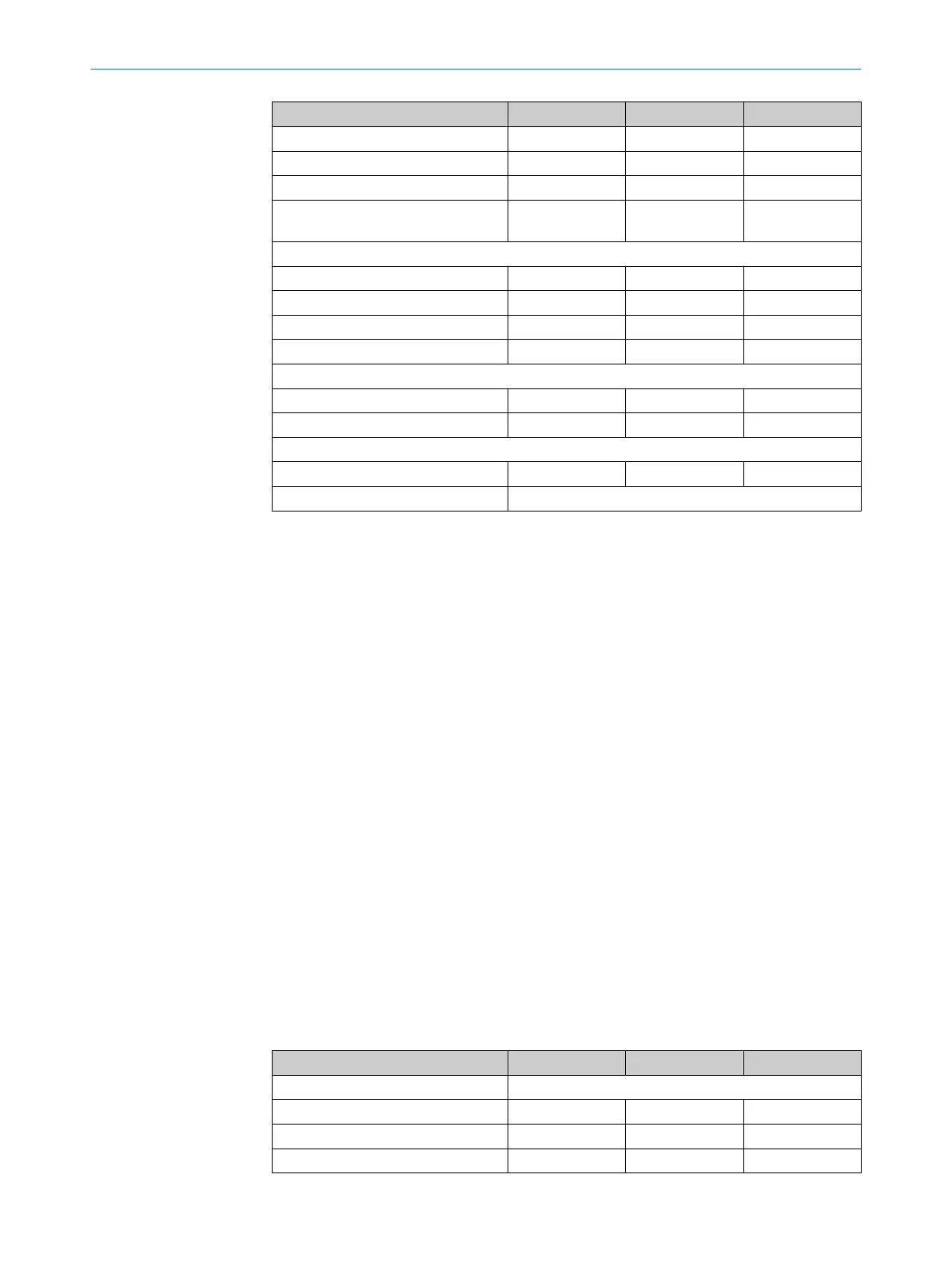
Minimum Typical Maximum
Test pulse width 120 µs 150 µs 300 µs
Test pulse rate 3 s
-1
5 s
-1
10 s
-1
Permissible cable resistance 1.29 Ω
Current consumption 3 A (Host/Guest/
Gue
st)
15)
Multifunctional connection
Input voltage
10)
HIGH (deactivated) 11 V 24 V 30 V
Input current HIGH 6 mA 15 mA 30 mA
Input voltage
10)
L
OW (active) -3 V 0 V 5 V
Input current LOW -2.5 mA 0 mA 0.5 mA
When used as EDM input
Permissible contactor dropout time 300 ms
Permissible contactor pull in time 300 ms
When used as control switch input (reset button)
Control switch actuation time 200 ms
Weight Depends on protective field height
1)
The minimum scanning range specifies a range in which a function is guaranteed to operate correctly and
s
afely under industrial conditions. A sufficient level of signal reserve to ensure very high availability is
included in the calculation.
2)
The typical scanning range specifies a range in which the safety light curtain operates correctly and
safely under industrial conditions. The level of signal reserve is enough to ensure high availability.
3)
The information in the table relates to 90° beam deflection per mirror. If you need more consultation on
mirror applications, please contact your SICK contact. É Do not use deflector mirrors if beading water or
heavy contamination on the deflector mirror is to be expected.
4)
SELV/PELV safety/protective extra-low voltage.
5)
In order to fulfill the requirements of the relevant product standards (e.g. IEC 61496-1), the external volt‐
a
ge supply of the devices (SELV) must be able to bypass events, including a power outage of 20 ms. The
power supply unit must ensure reliable network separation (SELV/PELV) and current limiting of max. 4 A.
Power supply units according to EN 60204-1 fulfill this prerequisite. Suitable power supply units are avail‐
able as accessories from SICK.
6)
Within the limits of U
V
.
7)
For more detailed information on the exact configuration of your machine, please contact your relevant
SIC
K subsidiary.
8)
The performance level does not include any specific requirements regarding aspects such as optical per‐
formance features.
9)
Applies for the voltage range between -30 V and +30 V.
10)
According to IEC 61131-2.
11)
At the male device connector
12)
In the event of a fault (interruption of the 0 V cable), the leak current at most flows in the OSSD cable.
The downstream control element must detect this state as LOW. An FSPLC (fail-safe programmable logic
controller) must detect this state.
13)
If the switching sequence is low, the maximum permissible load inductance is higher.
14)
When active, the outputs are tested cyclically (brief LOW). When selecting the downstream controllers,
make sure that the test pulses do not result in deactivation when using the above parameters.
15)
Maximum current consumption of a system with 1200 mm protective field height and a resolution of
14 mm.
Operating data
T
able 18: Operating data
Minimum Typical Maximum
System connection M12×4 male connector + FE
Length of cable 20 m
Wire cross-section 0.34 mm
2
Bend radius 45 mm
13 TECHNICAL DATA
90
O P E R A T I N G I N S T R U C T I O N S | miniTwin4 8012624/10OM/2018-08-09 | SICK
Subject to change without notice