1. Unplug the connecting cable from the MLG-1 sender. Remember to make a note of
the wire colors and terminal numbers of the MLG-1.
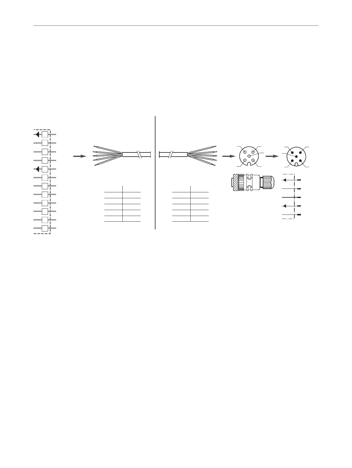
2. Connect the connecting cable to the 5-pin M12 female connector as follows:
■
Terminal 1 wire of MLG-1 → pin 1 of M12 female connector
■
Terminal 2 wire of MLG-1 → pin 3 of M12 female connector
■
Terminal 3 wire of MLG-1 → pin 2 of M12 female connector
■
Terminal 4 wire of MLG-1 → pin 5 of M12 female connector
■
Terminal 5 wire of MLG-1 → pin 4 of M12 female connector
3. Using the connecting cable, connect the M12 female connector to the M12 male
connector of the MLG-2.
L+
M
Sync B
TEST
nc
nc
nc
nc
nc
nc
nc
Sync A
1
2
3
4
5
6
7
8
9
10
11
12
MLG-1 MLG-2
1
1
43
5
2
3
DOS-1205-G
(6009719)
1
2
3
4
5
2 3
1
3
2
5
4
1
2
3
4
5
1 2
1
2
3
4
5
L+
Sync_A
M
Sync_B
Test_In
1
2
4
3
5
4
1
4 3
5
2
1
2
3
4
5
2
1
2
3
4
5
2
Figure 14: MLG-1, replacing a sender that has a terminal compartment
1
Terminal compartment on MLG-1 sender
2
Connecting cable for MLG-1 sender
3
M12 female connector, 5-pin, A-coded, e.g., DOS-1205-G (part number 6009719); to be ordered separately
4
M12 male connector, 5-pin, A-coded on MLG-2 sender
ELECTRICAL CONNECTION 6
8020351.ZLW3/2017-05-03 | SICK T E C H N I C A L I N F O R M A T I O N | The MLG-2 as a replacement product for the MLG-1 and XLG
23
Subject to change without notice