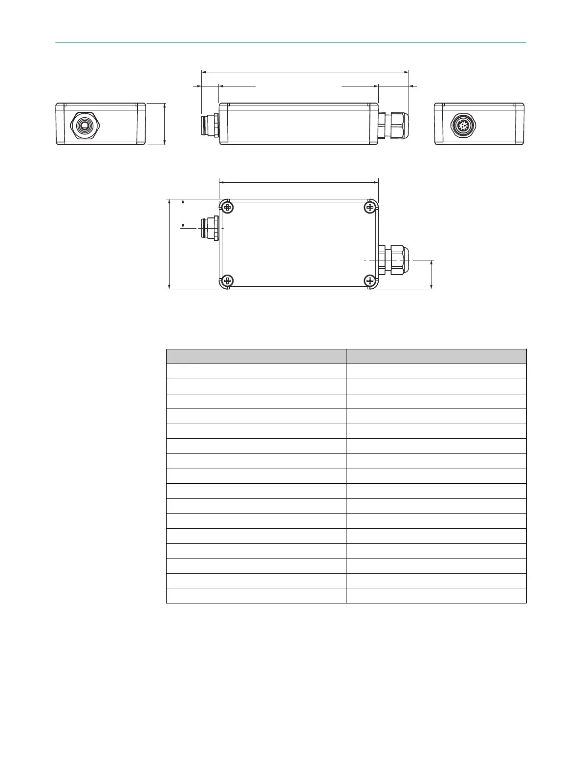
30 (1.18)
150 (5.91)
115 (4.53)
65 (2.56)
21
(0.83)
21
14 (0.55)
21
(0.83)
21 (0.83)
Figure 13: Dimensions of the “AFB” terminal box (part number 2082790)
The terminal box has 17 terminals.
Table 14: Terminals in the terminal box
1 SyncA
2 SyncB
3 L+
4 M
5 Q1
6 Q2
7 Q3
8 Q4
9 Q5
10 Q6
11 Reserved (Q7 for special applications)
12 IN1
13 IN2
14 RS485_A
15 RS485_B
16 Reserved (CAN_H for special applications)
17 Reserved (CAN_L for special applications)
6.4 Connecting the M12 female connector
In the case of MLG variants that feature a terminal compartment, a 5-pin, M12 female
connector is available to enable replacement of the sender (see "Overview of accesso‐
ries required", page 19).
To carry out the replacement process, proceed as follows:
6 ELECTRICAL CONNECTION
22
T E C H N I C A L I N F O R M A T I O N | The MLG-2 as a replacement product for the MLG-1 and XLG 8020351.ZLW3/2017-05-03 | SICK
Subject to change without notice