To carry out the replacement process, proceed as follows:
1. Unplug the connecting cable from the MLG-1 receiver. Remember to make a note
of the wire colors and terminal numbers of the MLG-1.
2. Plug the connecting cable into the “AFB” terminal box as shown below (see
figure 12, page 21).
■
Please note that the wiring is dependent on the MLG variant.
■
To make the wiring process easier, you can remove the terminal strips.
3. Connect the “AFB” terminal box to the 12-pin connecting cable (M12 male connec‐
tor) of the MLG-2.
4. To configure the MLG-2, you will need a PC that has SOPAS ET installed. Connect
this PC to the RJ45 female connector on the terminal box via an Ethernet cable
(part number 6026084).
MLG-1 MLG-2
3
4
6
L+
M
Sync B
IN1 / Teach-in
IN2
Q1
Q2
Q3
Q4
Q5 / RS-485A
Q6 / RS-485A
Sync A
1
2
3
4
5
6
7
8
9
10
11
12
1
1
6
2
12
1
2
12
1
2
3
4
5
1 2
6
7
8
9
10
11
12
1
2
3
4
5
6
7
8
9
10
11
12
1
2
3
4
5
2
3
6
7
8
9
10
11
12
3
4
1
2
12
13
5
6
7
8
9
10
4
3
4
1
2
12
13
7
8
9
10
14
15
MLGx-xxxxE2
MLGx-xxxxF2
MLGx-xxxxI2
MLGx-xxxxT2
SyncA
SyncB
M
Q1
Q2
Q3
Q4
Q5
Q6
Reserved (Q7)
IN1
L+
1
2
3
4
5
6
7
8
9
10
11
12
13
14
15
16
17
IN2
RS485_A
RS485_B
Reserved (CAN_H)
Reserved (CAN_L)
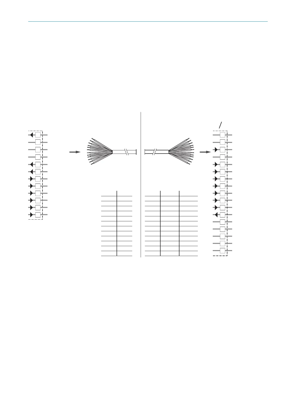
Figure 12: MLG-1, replacing a receiver that has a terminal compartment
1
Terminal compartment on MLG-1 receiver
2
Connecting cable for MLG-1 receiver
3
Connection to the “AFB” terminal box for variants MLGx-xxxxE2 and MLGx-xxxxF2
4
Connection to the “AFB” terminal box for variants MLGx-xxxxI2 and MLGx-xxxxT2
ELECTRICAL CONNECTION 6
8020351.ZLW3/2017-05-03 | SICK T E C H N I C A L I N F O R M A T I O N | The MLG-2 as a replacement product for the MLG-1 and XLG
21
Subject to change without notice