6 Electrical installation
6.1 Wiring instructions
NOTE
Pre-assembled cables can be found on the product page.
The call is made via the SICK Product ID: pid.sick.com/{P/N}/{S/N}
{P/N} corresponds to the part number of the product, see type label.
{S/N} corresponds to the serial number of the product, see type label (if indicated).
NOTICE
Faults during operation and defects in the device or the system
Incorrect wiring may result in operational faults and defects.
■
Follow the wiring notes precisely.
The enclosure rating stated in the technical data is achieved only with a screwed plug
connector or protective cap.
Configure the circuits connected to the device as ES1 circuits or as SELV circuits (SELV
= Safety Extra Low Voltage). The voltage source must meet the requirements of ES1
and PS2 (EN62368-1) or SELV and LPS (EN60950-1).
Connect the connecting cables in a de-energized state. Do not switch on the supply
voltage until installation is complete and all connecting cables are connected to the
device and control.
6.2 Pin assignment
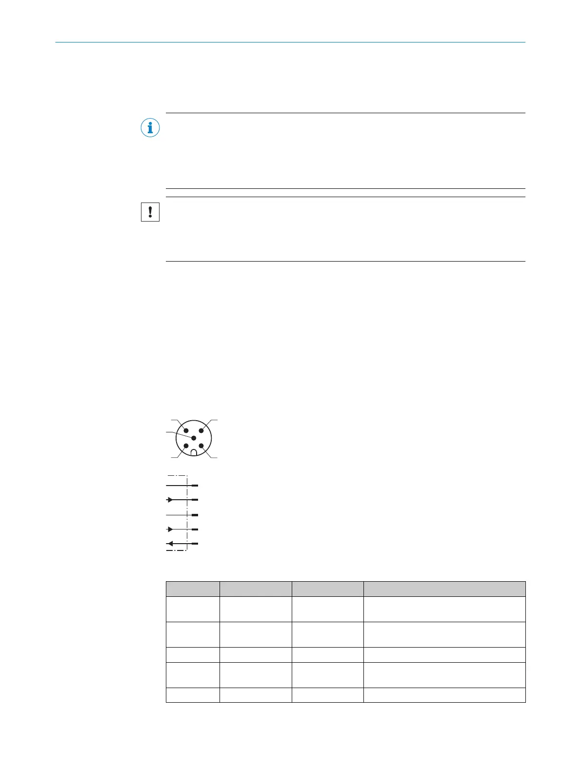
L+
1
brn
M
3
blu
Q1/C
4
blk
Q2/Q
A
2
wht
In1
5
gra
Figure 6: Connection diagram, 5-pin male connector
Contact Signs Wire color Description
1 L+ Brown Supply voltage, see "Technical data",
page 51
2 Q2/Q
A
1)
White Output 2: digital output 2 (push-pull
stage) / analog output
1)
3 M Blue Supply voltage: 0 V
4 Q1/C Black Output 1: Digital output 1 (push-pull
stage) / IO-Link
5 In1 Gray Input 1
1)
Q
A
is not available for devices without an analog output, see "Device variants", page 13.
6 ELECTRICAL INSTALLATION
18
O P E R A T I N G I N S T R U C T I O N S | OD2000 8026231/1I18/2023-01-05 | SICK
Subject to change without notice