10.2 Dimensional drawing
PWR
Q2/Q
A
Q1
5
6
7
8
9
1
ß
4
3
2
1
27 (1.06)
50 (1.97)
2x Ø 4.5
(0.18)
12.5
(0.49)
4.5
(0.18) 25.4 (1.00)
10
(0.39)
60 (2.36)
55.3 (2.18)
50.8 (2.00)
Ø
4.5
(0.18)
35.3 (1.39)
28.3 (1.11)
34 (1.34)
25.8 (1.02)
36.5 (1.44)
18.7 (0.74)
26.3 (1.04)
Ø 0.7 (0.03)
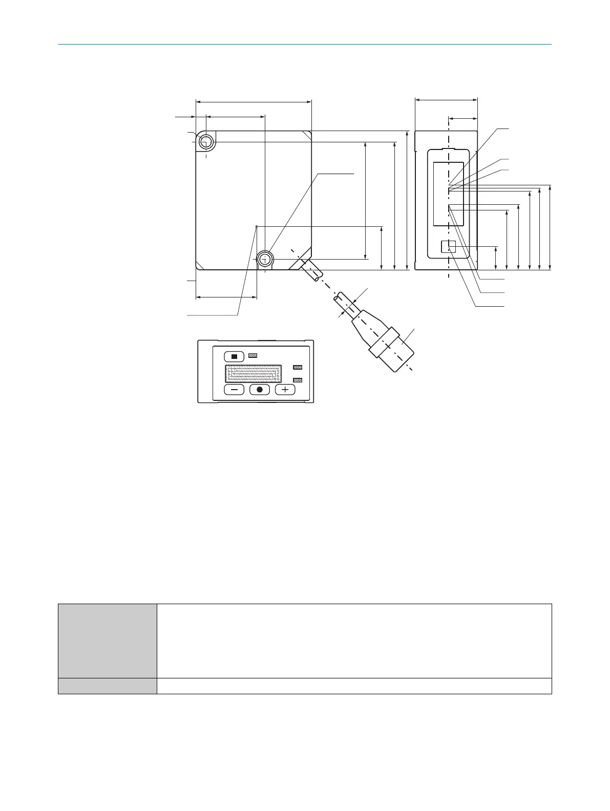
Figure 18: structure and device dimensions, unit: mm (inch), decimal separator: period
1
Fixing holes (M4)
2
Ventilation opening (do not cover)
3
Device zero point (distance = 0mm)
4
Device cable (length: 300mm) with male connector, M12, 5-pin, A-coded
5
Center of optical axis, receiver (device type OD2000-350, OD2000-700)
6
Center of optical axis, receiver (device type OD2000-245)
7
Center of optical axis, receiver (device type OD2000-130)
8
Center of optical axis, receiver (device type OD2000-050)
9
Center of optical axis, receiver (device type OD2000-030)
ß
Center of optical axis, sender
10.3 Performance
Measuring range
1)
OD2000-030xxxx: 25mm…35mm
OD2000-050xxxx: 40mm…60mm
OD2000-130xxxx: 60mm…200mm
OD2000-245xxxx: 70mm…420mm
OD2000-350xxxx: 100mm…600mm
OD2000-700xxxx: 200mm…1,200mm
Measuring object Natural objects
10 TECHNICAL DATA
52
O P E R A T I N G I N S T R U C T I O N S | OD2000 8026231/1I18/2023-01-05 | SICK
Subject to change without notice