Figure 4: Triangulation principle
1
Receiver
2
Receiver optics
3
Object
4
Sender
The triangulation principle is based on distance measurement through angle calcula‐
tion. The device emits a light beam. When the emitted light beam hits an object,
the light beam is reflected on its surface. The light reflected from the object hits the
light-sensitive receiver in the device at an angle that depends on the distance. Based
on the angle between the sending and receiving beam direction, the distance to the
object is determined via triangulation.
3.4.2 Output of measured values and parameterization
The distance determined is transmitted via the IO-Link interface. The analog signal
output converts the distance value into an output signal proportional to the distance.
The device signals via the digital outputs whether parameterizable switching limits and
distance values have been reached.
Measurement, diagnostic and device data can be queried and parameter settings can
be made via the OLED display. The device can be parameterized via the display, the
IO-Link interface and SOPAS ET.
3.5
Display and control elements
Overview
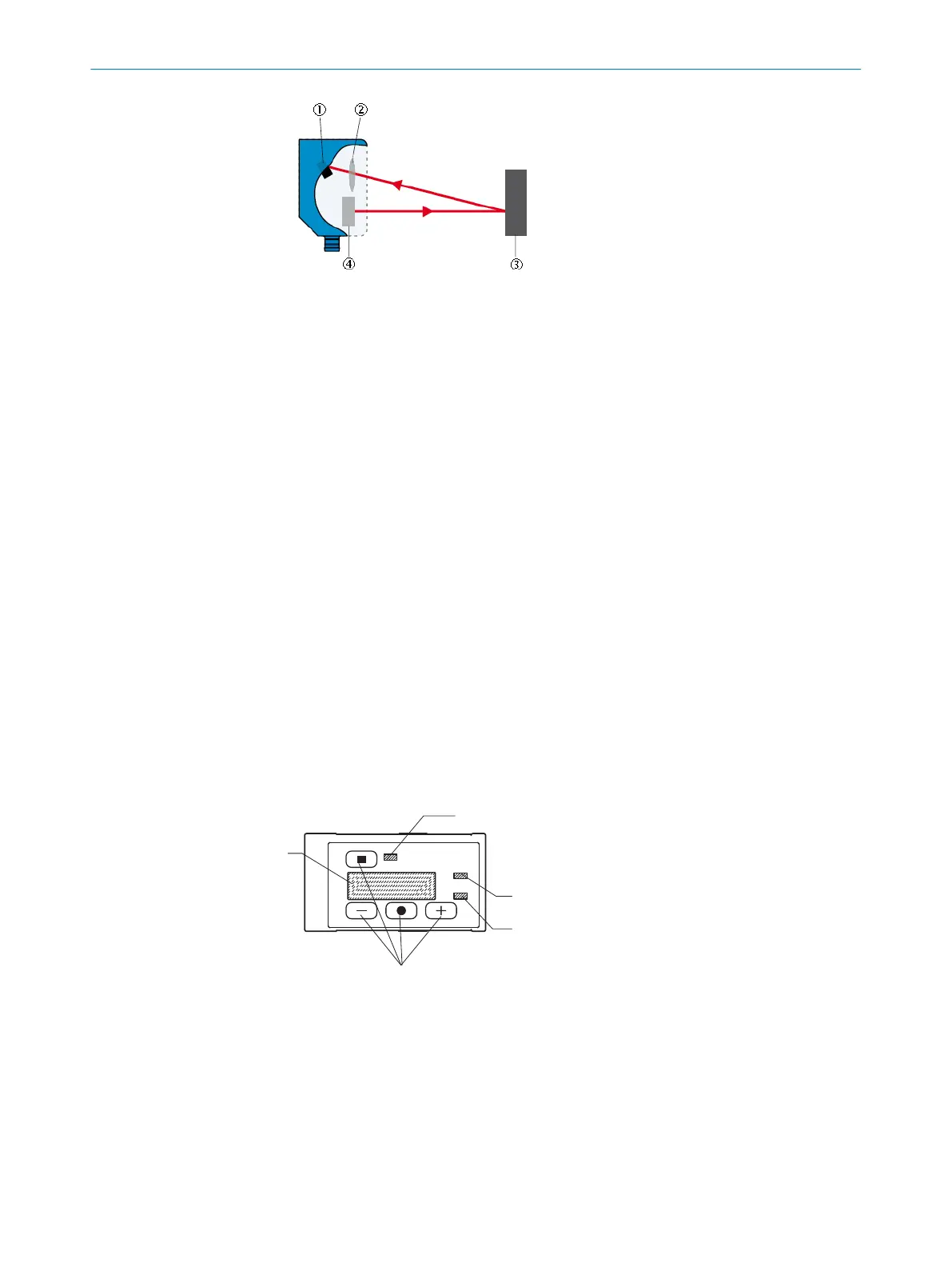
Figure 5: Display and control elements
1
PWR status LED (green)
2
Status LED Q2/Q
A
(orange)
3
Q1 status LED (orange)
4
Operating pushbuttons
5
Display
3 PRODUCT DESCRIPTION
14
O P E R A T I N G I N S T R U C T I O N S | OD2000 8026231/1I18/2023-01-05 | SICK
Subject to change without notice