SYSTEM DESCRIPTION 3
8022965-17I6/2020-03-19|SICK
Subject to change without notice
ORIGINAL OPERATING INSTRUCTIONS| VMS4200/5200 (Multicontroller)
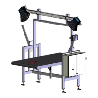
Fig. 7: Cabinet for VMS4200/5200 (Multicontroller)
Legend
1 Terminals for voltage supply IN (100–264 V AC / 50–60 Hz)
2 Air inlet for cooling (with filter mat and cooler)
3 Terminals (24 V DC) and fuse module OUT
4 SIM2000 system controller with alibi memory
5 Power supply unit for supplying voltage to the SIM2000 and 2D LiDAR
sensors
6 Air outlet for cooling (with filter mat)
7 Air outlet for cooling (with filter mat)
8 Power supply unit for supplying voltage to the LFT display
9 SIM2000 dimensioning controller
10 Ethernet switch for connecting the system components
11 Air inlet for cooling (with filter mat and cooler)
12 Ethernet switch for connecting external scanners.
Cabinet of the
VMS4200/5200
(Multicontroller)