Operating mode
Drive function SERVO / VECTOR VF
Operating modes ▶ Speed Mode
▶ Current reference value
▶ Profile Velocity Mode
▶ Interpolated position control
▶ Electronic gear
▶ Speed Mode
Software Connection
Drive function SERVO / VECTOR VF
Parameterization in soft‐
ware
drivemaster2
▶ USB connection
▶ RS232 connection
▶ SERVOLINK 4 (only optical fibers)
Communication channels
Drive function SERVO / VECTOR VF
Control channel ▶ Digital inputs
▶ Serial interface / RS485 / USB
▶ SERVOLINK 4
▶ CAN bus
▶ DNC 8 Byte Telegram
Setpoint channel
▶ Analog inputs
▶ Serial interface / RS485 / USB
▶ Internal setpoints
▶ Encoder 0
(only with software package L04001 /
F04006)
▶ SERVOLINK 4
▶ CAN bus
▶ DNC 8 Byte Telegram
▶ Analog inputs
▶ Serial interface / RS485 / USB
▶ Internal setpoints
▶ SERVOLINK 4
▶ CAN bus
▶ DNC 8 Byte Telegram
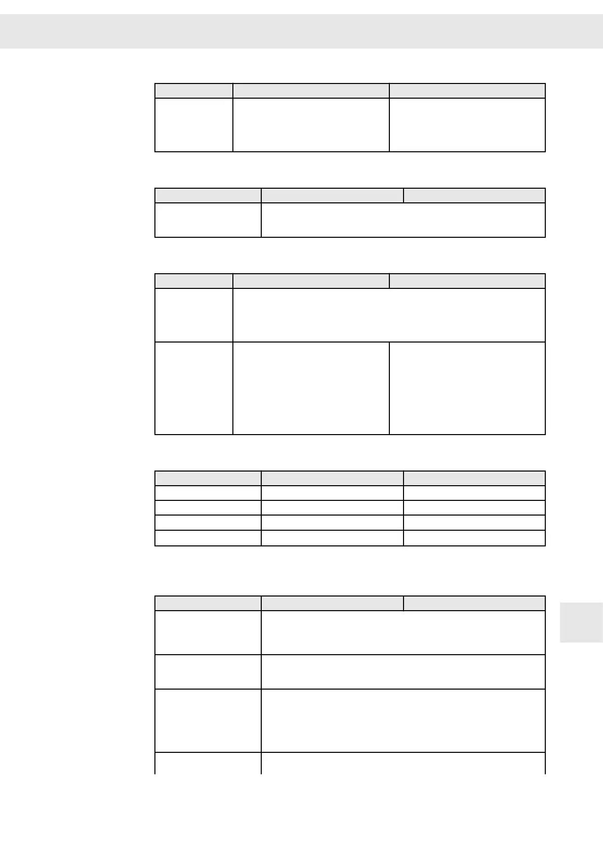
Control
Drive function
SERVO / VECTOR VF
Operating frequency 8 / 16 kHz 8 / 16 kHz
All-digital current control 16 kHz 8 / 16 kHz
All-digital speed control 16 kHz (62.5 µs) -
All-digital position control
4 kHz (250 µs)
(1)
-
(1)
Only with interpolated position control and electronic gear.
Interfaces
Drive function
SERVO / VECTOR VF
Digital inputs ▶ 9 inputs 24 V incl. 1 input (latch function 250 kHz (4 µs) sampling)
▶ 12 – 24 V high / 0 – 5 V low
▶ Sampling 4 kHz (250 µs)
▶ Function to be configured via software
Digital outputs
▶ 5 outputs 24 V (max. 100 mA per output)
▶ Sampling 4 kHz (250 µs)
▶ Function to be configured via software
Analog inputs
▶ 2 differential signal inputs
▶ Operating range ±10 V
▶ Maximum range ±12 V
▶ Resolution internal 14 Bit
▶ Sampling 4 kHz (250 µs)
▶ Function to be configured via software
Analog outputs
▶ 2 outputs
▶ Operating range 0 – 10 V
W
Appendix
Drive System SD2S - Hardware Description 0362X49xy / 0362129xy 103
13.A
 Loading...

