e4595e14
37
Fire & Security Products
Siemens Building Technologies Group
05.2003
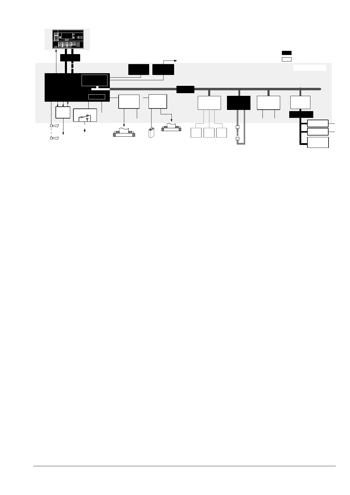
K3I090
Pager
–> see page 86
or
internal or
external printer
CT1142
(operation = separate C-Bus station)
Details see page 42
B2F020
I-Bus
FBF FSK HM
E3L030
1..2
Z3B171
1..........8
E3M...
C-Bus
CPU
E3X10.
24V
AX12..
12
E3I020
RS232
E3G...
E3L...
250VAC 10A
Basic equipment
Option
Mains
Batteries
Driver
RT
24V
Fire control
installations
VdS peripheral
equipment
24V
Battery
charging mdule
LON synoptic converter
LON I/O card
Floor indicator terminal
–> see page 72ff
Printer
–> see page 82
RT = Remote transmission
CC1142/43
LON-Bus
K3I050
B3Q580/
B3Q59x
E3I040
K3I110
Modules H67G601 and H67G611
Control and operation
E3X101 546674 Master module EPROM and RAM set separately
K3N010 522818 RAM extension card 1MB-RAM additional to E3X101
Z3S070 504823 RAM set 2x512Kx8Bit to E3X101
E3X102 629025 Master module Flash-ROM and 1MB-RAM equipped
E3X103 629038 Master module Flash-ROM and 2MB-RAM equipped
B3Q... Control terminal AlgoPilot all variants of the AlgoPilot see page 42
H26T... Plexiglass door to AlgoPilot B3Q... optional see page 42
Z5B... ...... Inscription set according to language see page 45, 46
–––––––––––––––––––––––––––––––––––––––––––––––––––––––––––––––––––––––––––––––––––––––––––––––––––––––––––––––––––––––––––––––––––––
EPROM sets and Flash programm files
CCQ00xxx 577627 EPROM set to ’CC1142’ for Main CPU E3X101
CCW00xxx 577630 EPROM set to ’CC1143’ for Main CPU E3X101 with K3N010
CCX00xxx (OSS) Flash programm file for Main CPU E3X102
CCY00xxx (OSS) Flash programm file for Main CPU E3X103
–––––––––––––––––––––––––––––––––––––––––––––––––––––––––––––––––––––––––––––––––––––––––––––––––––––––––––––––––––––––––––––––––––––
Line modules according to detector series for details referring line modules see page 59
–––––––––––––––––––––––––––––––––––––––––––––––––––––––––––––––––––––––––––––––––––––––––––––––––––––––––––––––––––––––––––––––––––––
LON module for details referring floor indicator terminal see page 72
–––––––––––––––––––––––––––––––––––––––––––––––––––––––––––––––––––––––––––––––––––––––––––––––––––––––––––––––––––––––––––––––––––––
Control modules if more than 7 progr. control outputs are required for details referring control modules see page 66
–––––––––––––––––––––––––––––––––––––––––––––––––––––––––––––––––––––––––––––––––––––––––––––––––––––––––––––––––––––––––––––––––––––
Extinguishing modules and operation for details referring extinguishing see page 79
–––––––––––––––––––––––––––––––––––––––––––––––––––––––––––––––––––––––––––––––––––––––––––––––––––––––––––––––––––––––––––––––––––––
Interfaces as far as the space available allows installation
E3H020 546658 Gateway ’CERLOOP’ double Europe card (requires 2 module spaces) see page 75
E3I020 460239 RS232 module for connection of printer B2Q191 or non-Cerberus printer
K3I090 510820 Pager interface for connection of paging system/pager and internal/external printer
–––––––––––––––––––––––––––––––––––––––––––––––––––––––––––––––––––––––––––––––––––––––––––––––––––––––––––––––––––––––––––––––––––––
Power supply for calculation of the emergency power operating period see page 91
B2F020 470588 Converter 115/230V
AC>29.6VDC 6A
B1F120 495233 Converter 115/230V
AC>24VDC 3A generally for fire control system supply
AX1201 225487 Battery 12V/27Ah
AX1209 462936 Battery 12V/42Ah
Z3I450 484273 Mains socket ”CH”
Z3I041 496290 Surge protector set option
–––––––––––––––––––––––––––––––––––––––––––––––––––––––––––––––––––––––––––––––––––––––––––––––––––––––––––––––––––––––––––––––––––––
Cabinet/Accessories for details referring cabinets see page 55
H67G601 495550 Cabinet set ’Door without cutout’ for separate control terminal
H67G611 495660 Cabinet set ’door with cutout’ for installation in control terminal
H67G620 577863 Cabinet set for marine
H67E101 509705 Module chassis compl. for H67 ... for installation in external cabinets
H23B010 476210 Cover essential or H23B040 or B3Q321 or B3R051
H23B040 484590 Information module brief operating instructions
B3Q321 565684 Fire department control terminal ”CH” only CH
B3R051 490513 Parallel indicator terminal ”2x24 indicators” option
Z3I350 475538 Cable set for H47/H67 essential
Z3I380 475567 I-Bus flat cable + supply cable ”long” to connect module level 4.. with level 3..
Z1I040 475512 Connection cable 9 cond. with card holder, 0.8m for internal pre-wiring
Z1I050 475525 Connection cable, 19 cond. with card holder, 0.8m for internal pre-wiring
Z1I070 525815 Connection cable, 4 cond. with card holder, 0.8m for internal pre-wiring
Z3B171 484383 Relay module 1 x 250VAC/10A intermediate relay for fire control installations
Z3I330 475156 Terminal block, 2x20 terminals
Z3I420 483818 Intermediate connecting terminal block for additional free terminals
Z3I570 495644 Support rail ’TS35’ 133 mm with bracket for up to 8 Z3B171 relays
Z3G270 566120 Marinekit
Pre-configured cabinet
CC1142-NL547000 Control unit in H67 housing pre-configured for ’NL’ requirements

 Loading...


