5 System parameters
MICROMASTER 430 Operating Instructions
66 6SE6400-5AC00-0BP0
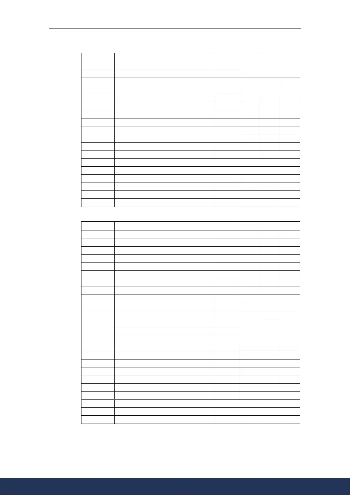
ParNr ParText Default Level DS QC
P1216 Holding brake release delay 1.0 2 T N
P1217 Holding time after ramp down 1.0 2 T N
P1232[3] DC braking current 100 3 CUT N
P1233[3] Duration of DC braking 0 3 CUT N
P1234[3] DC braking start frequency 650.00 3 CUT N
P1236[3] Compound braking current 0 3 CUT N
r1242 CO: Switch-on level of Vdc-max - 3 - -
P1240[3] Configuration of Vdc controller 1 3 CT N
P1243[3] Dynamic factor of Vdc-max 100 3 CUT N
P1254 Auto detect Vdc switch-on levels 1 3 CT N
P1253[3] Vdc-controller output limitation 10 3 CUT N
r1261 BO: Contactor control word - 2 - -
P1260[3] source of changeover control 0 2 CT N
P1262[3] Bypass dead time 1.000 2 CUT N
P1263[3] De-Bypass time 1.0 2 CUT N
P1264[3] Bypass time 1.0 2 CUT N
P1265[3] Bypass frequency 50.00 2 CT N
P1266[3] BI: Bypass command 0:0 2 CT N
Motor Control (P0004 = 13)
ParNr ParText Default Level DS QC
r0020 CO: Act. frequency setpoint - 3 - -
r0021 CO: Act. frequency - 3 - -
r0022 Act. rotor speed - 3 - -
r0024 CO: Act. output frequency - 3 - -
r0025 CO: Act. output voltage - 3 - -
r0027 CO: Act. output current - 3 - -
r0032 CO: Act. power - 3 - -
r0038 CO: Act. power factor - 3 - -
r0056 CO/BO: Status of motor control - 3 - -
r0061 CO: Act. rotor speed - 3 - -
r0065 CO: Slip frequency - 3 - -
r0067 CO: Act. output current limit - 3 - -
r0071 CO: Max. output voltage - 3 - -
r0086 CO: Act. active current - 3 - -
P0095[10] CI: Display PZD signals 0:0 3 CT N
r0096[10] PZD signals - 3 - -
P1300[3] Control mode 1 3 CT Q
P1310[3] Continuous boost 50.0 3 CUT N
P1311[3] Acceleration boost 0.0 3 CUT N
P1312[3] Starting boost 0.0 3 CUT N
P1316[3] Boost end frequency 20.0 3 CUT N
P1320[3] Programmable V/f freq. coord. 1 0.00 3 CT N
P1321[3] Programmable V/f volt. coord. 1 0.0 3 CUT N
P1322[3] Programmable V/f freq. coord. 2 0.00 3 CT N
www.eltra-trade.com
+421 552 601 099
info@eltra-trade.com

 Loading...


