Connecting-up
5.3 EMC-compliant installation
Power Module PM240-2
56 Hardware Installation Manual, 12/2015, A5E33294624B AD
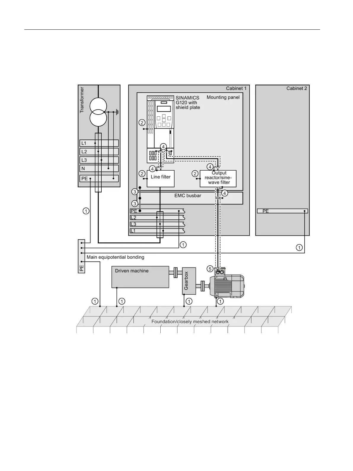
Diagrams for grounding and high-frequency equipotential bonding measures
The following diagram illustrates all grounding and high-frequency equipotential bonding
measures using the example of a cabinet with a SINAMICS G120.
Conventional grounding without any special HF properties
High-frequency equipotential bonding measures
Electrically conductive connection to the mounting panel through the largest possible surface
Connect the shield through a large contact surface and ground
Connect the shield through an electrically conductive heavy-gauge threaded joint (gland) and
Figure 5-9 Grounding and high-frequency equipotential bonding measures in the drive system and
in the plant
 Loading...