Connection
6.3 Connecting the power supply
SIMATIC MV500
80 Operating Instructions, 06/2018, C79000-G8976-C494-01
The Power-IO RS232 cable is used for the power supply, for connection to the DI/DQ
connections and, for example, for the communication connection of an S7 controller via the
RS232 interface.
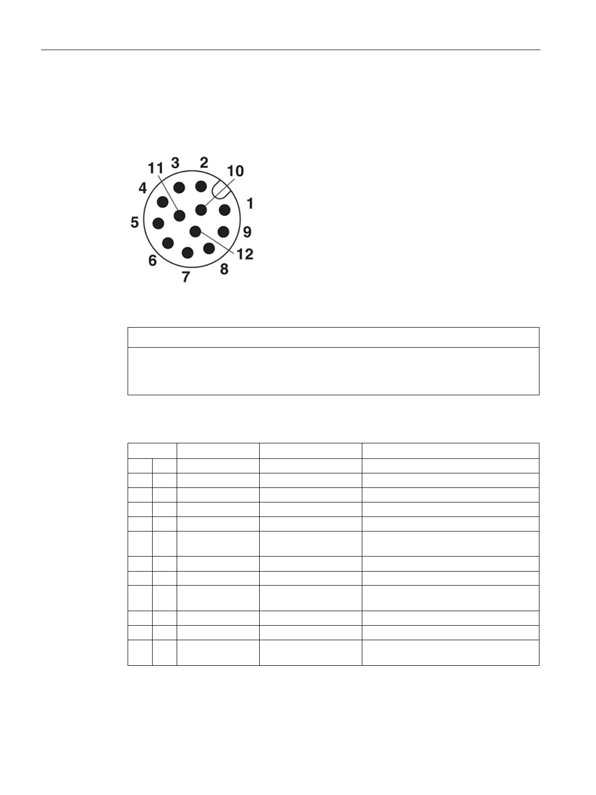
Figure 6-2 Pin assignment of the Power-IO RS232 connector on the optical reader
Connect "IN_COMMON" or "OUT_COMMON"
In order to be able to use the inputs and outputs described below, you must connect the
"IN_COMMON" or "OUT_COMMON" signals.
Table 6- 1 Pin assignment Power-IO RS232 cable, M12 (female, 12-pin)
Reference point 0 V or 24 V for inputs
Send line RS422 TxD positive
Send line RS422 TxD negative
Reference point 0 V or 24 V for outputs
6 F Pink RS232 TxD /
Send line RS232 / Receive line RS422
7 G Blue DC 0V 0 V DC power supply
9 J Black STROBE (OUTPUT) Signal output for connecting the external
Trigger input / digital input 1
12 M Red/blue RS232 RxD /
Receive line RS232 / RS422 RxD nega-

 Loading...


